
A car that pulls hard one day and feels flat the next, an overboost code after a hot lap, a tractor that loses power on a long climb: a large share of turbo complaints come down to boost control, not the turbo itself. On fixed-geometry turbochargers that control runs through the wastegate, a valve that diverts exhaust gas around the turbine. This guide covers the hardware, the ECU control loop, a practical diagnostic routine and the related fault codes.
Fixed-geometry turbos and why they need a wastegate
The turbine and compressor sit on one shaft, so turbine speed sets boost. A turbo that spools early would overspeed and overboost at high rpm if every bit of exhaust kept driving it. Opening the wastegate sends part of the flow past the turbine and caps boost. (Many diesels use a variable geometry turbo instead, with adjustable guide vanes; see our VGT guide from 13 October.)
Wastegate types
Internal wastegates are a flap and port inside the turbine housing, linked to an actuator by a rod. They are the standard on production vehicles. External wastegates are standalone valves on the exhaust manifold, with a larger valve and their own spring housing. They offer more bypass flow and steadier control at high boost, which is why they appear on race engines and high-power conversions.
Actuation: from spring and diaphragm to electric motor
Pneumatic with boost control solenoid
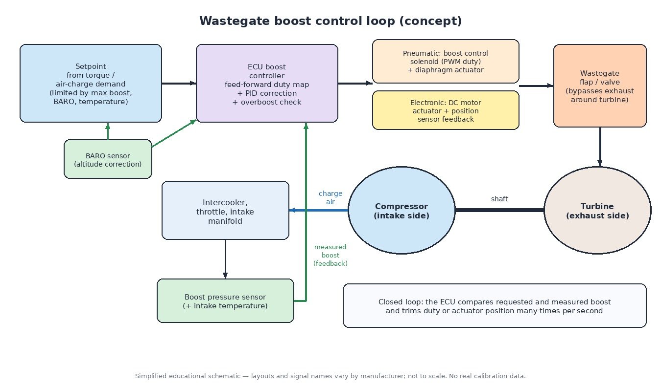
A spring inside the actuator keeps the wastegate shut. Pressure on the diaphragm, taken from the compressor outlet on most petrol engines, pushes against it. With no electronic help the turbo makes roughly spring pressure, known as base boost. A boost control solenoid (frequency valve; the N75-type valve is a common example) sits in the actuator line. The ECU pulses it with PWM at a fixed frequency, and the duty cycle decides how much pressure the actuator sees. Changing duty lets the ECU hold the gate shut longer and run boost above base. Diesels with wastegates often work with vacuum and an electro-pneumatic converter instead.
Electronic actuator with position feedback
An electric wastegate actuator combines a DC motor, gear train and position sensor. The ECU sets a target position, watches the sensor and corrects. Because it does not need boost or vacuum to move, it can open the gate at light load to reduce backpressure and hold position accurately at any load. After replacement it normally needs a learn or adaptation routine.
Inside the ECU: closed-loop boost control
The requested boost is derived from the torque or air-charge demand: the ECU works out the cylinder air mass required, then the manifold pressure that delivers it. That request is limited by:
- a maximum boost map over rpm,
- intake air and coolant temperature corrections,
- a compressor pressure ratio or turbo speed limit, which uses ambient pressure from the BARO sensor to cut the target at altitude.
The controller then combines a feed-forward (pilot) map, giving the expected duty or position for this rpm and target, with PID-style correction based on the error from the boost pressure sensor. Integral limits and learned adaptations keep it stable as parts age. An overboost monitor watches for actual boost above target for too long, then opens the wastegate, reduces torque and sets P0234. A sustained shortfall sets P0299.

Workshop diagnostic routine
- Read all codes and freeze-frame data. Electrical codes (P0243–P0246, P0045) point to circuits; P0234/P0299 point to the system.
- Key on, engine off: boost sensor and BARO should both read ambient pressure. A mismatch suggests a sensor fault.
- Log requested vs actual boost with duty or position on a full-load pull in third or fourth gear. Low boost with the command at its limit means the hardware cannot follow.
- Smoke test the intake tract from the compressor outlet to the intake manifold, including intercooler, couplers and the bypass valve.
- Check the actuator: hose routing, solenoid resistance, diaphragm leak-down with a hand pump, rod movement and flap play. On electric actuators, run the adaptation and watch the position signal.
- Only then suspect the turbo: shaft play, damaged compressor wheel or exhaust leaks before the turbine.
Differences by vehicle type
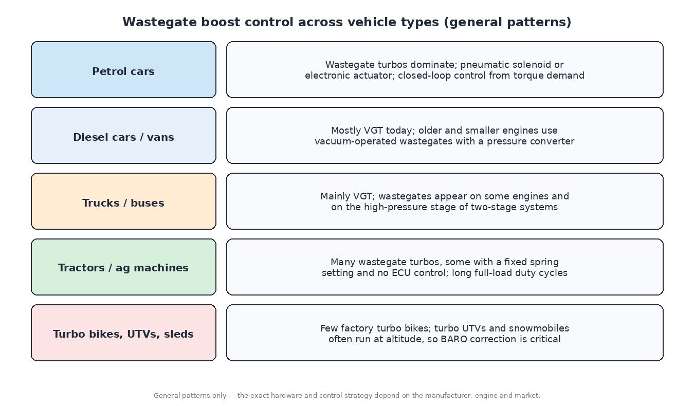
- Petrol cars: wastegate turbos are the norm, with pneumatic or electric actuators and full closed-loop control.
- Diesel cars and vans: mostly VGT now; older and small engines use vacuum wastegates.
- Trucks and buses: mainly VGT, with wastegates on some engines and in two-stage systems.
- Agricultural machines: wastegate turbos are widespread, some purely spring-set without ECU control; sustained full load makes temperature limits critical.
- Motorbikes, ATVs/UTVs and snowmobiles: factory turbo bikes are rare, but turbo side-by-sides and snowmobiles exist and often work at altitude, where BARO correction protects the turbo.
Related fault codes (DTCs)
Generic OBD-II codes per SAE J2012. Exact wording and code usage vary between manufacturers.
| Code | Meaning | Typical causes |
|---|---|---|
| P0234 | Turbocharger/Supercharger “A” Overboost Condition | Wastegate stuck closed, faulty boost control solenoid, split or misrouted actuator hose, target beyond hardware capability |
| P0299 | Turbocharger/Supercharger “A” Underboost Condition | Boost leaks, wastegate stuck open, weak actuator diaphragm, worn turbo, exhaust leak before the turbine |
| P0236 | Turbocharger/Supercharger Boost Sensor “A” Circuit Range/Performance | Reading implausible against BARO or the air model, contaminated sensor, leaking sensor seal |
| P0237 | Turbocharger/Supercharger Boost Sensor “A” Circuit Low | Open or grounded signal wire, missing 5 V reference, faulty sensor |
| P0238 | Turbocharger/Supercharger Boost Sensor “A” Circuit High | Signal shorted to voltage, open ground, faulty sensor |
| P0243 | Turbocharger/Supercharger Wastegate Solenoid “A” | Open or shorted solenoid coil, wiring or connector fault |
| P0244 | Turbocharger/Supercharger Wastegate Solenoid “A” Range/Performance | Sticking or internally leaking solenoid, blocked ports or filter |
| P0245 | Turbocharger/Supercharger Wastegate Solenoid “A” Low | Control circuit shorted to ground |
| P0246 | Turbocharger/Supercharger Wastegate Solenoid “A” High | Control circuit shorted to voltage or open, faulty solenoid |
| P0045 | Turbocharger/Supercharger Boost Control “A” Circuit/Open | Open circuit to the boost control solenoid or actuator, corroded connector |
| P2562 | Turbocharger Boost Control Position Sensor “A” Circuit | Actuator position sensor or wiring fault |
| P2563 | Turbocharger Boost Control Position Sensor “A” Circuit Range/Performance | Implausible position, sticking linkage, actuator not adapted after replacement |
| P0033 | Turbocharger/Supercharger Bypass Valve “A” Control Circuit | Open circuit to the electric bypass (recirculation) valve |
| P0034 | Turbocharger/Supercharger Bypass Valve “A” Control Circuit Low | Control circuit shorted to ground |
| P0035 | Turbocharger/Supercharger Bypass Valve “A” Control Circuit High | Control circuit shorted to voltage, faulty valve |
| P2261 | Turbocharger/Supercharger Bypass Valve “A” – Mechanical | Torn diaphragm or valve stuck open, venting boost to the compressor inlet |
| P2227 | Barometric Pressure Sensor “A” Circuit Range/Performance | Implausible ambient pressure reading, often a sensor inside the ECU; upsets altitude correction |
Tuning implications
Boost tuning means changing a set of related tables, not one value: boost targets, maximum boost and pressure-ratio limits, pilot duty or position maps, controller gains if response changes, and the overboost threshold, which must still protect the engine. Targets should stay within the compressor map and turbo speed limits, and altitude correction must remain active. Fuel, ignition and torque calibration have to follow the extra air. Mechanical health first: a leak or weak actuator will undo any file.
Looking for an original file or an engineered calibration? Browse the ECUFlashFiles shop.