
A diesel with unit injectors or unit pumps that idles rough, knocks, smokes or will not start is a regular sight in workshops that look after older TDIs, trucks and farm machinery. These systems are tough, but they fail in their own ways, and an expensive injector is often replaced when the real fault is wiring, a sensor or the fuel supply. This guide looks at unit injector and unit pump systems from a diagnostic angle: how they make pressure, what the ECU measures, and a step-by-step routine to find the real cause.
How the system makes pressure
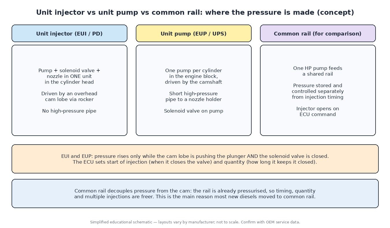
Instead of one high-pressure pump feeding a rail, these engines have one small pump per cylinder driven by a cam lobe. On a unit injector (EUI, or Pumpe-Düse on VW Group engines) the pump, a solenoid valve and the nozzle are a single unit in the cylinder head, worked by a rocker from the overhead camshaft. On a unit pump (EUP or UPS) each pump sits in the block, driven by the engine camshaft, and feeds a nozzle holder through a short high-pressure pipe.
As the cam pushes the plunger, fuel simply spills back while the solenoid valve is open. When the ECU closes the valve, pressure climbs rapidly, the nozzle opens and fuel is injected. When it releases the valve, injection stops. The closing moment sets the start of injection; the closed time sets the quantity.
What the ECU monitors
- Crank and cam position: every injection must happen on the right cam lobe, so the cam sensor is essential and a missing signal often means no start.
- Solenoid current: after a high pull-in current and a lower hold current, the waveform reveals when the valve actually closed. Bosch-type systems call this point BIP, and the ECU uses it to correct each cylinder’s timing.
- Cylinder balance: small speed differences between firing strokes show which cylinders produce more or less torque, and the ECU adjusts quantity per cylinder to smooth the idle.
- Fuel temperature, air mass or boost, coolant temperature and pedal position: the inputs for quantity, timing and smoke limits.

Common failure areas
Electrical
On engines where the injector loom runs inside the rocker cover, heat, vibration and oil attack the harness and connectors. Symptoms are intermittent: a cylinder drops out when hot, or circuit codes come and go. An open or shorted solenoid coil gives a hard circuit fault.
Hydraulic and mechanical
Worn plungers and valves, a sticking needle or poor spray pattern show up as high balance corrections, smoke or knock on one cylinder. Leaking injector seals can let fuel into the engine oil or combustion gas into the fuel. Worn cam lobes or rockers reduce the stroke available for injection, and a unit injector that was not adjusted correctly after fitting can cause the same symptoms as a faulty one.
Supply and data
Low feed pressure, air in the fuel or very hot fuel starve every cylinder at once. On many truck and machine engines a new injector also needs its trim or calibration code entered in the ECU, otherwise that cylinder will be out of balance.
Step-by-step diagnostic routine
- Read all codes, including manufacturer and J1939 codes, and note the freeze-frame conditions.
- At warm idle, compare cylinder balance or quantity correction values. One cylinder far from the others is your lead.
- Where the scan tool shows valve closure timing, compare it across cylinders.
- Measure solenoid resistance against the service data and wiggle-test the harness and connectors.
- Check feed pressure and fuel condition, and test for fuel in the oil.
- Check compression or do a relative compression test before condemning an injector, since low compression also skews balance values.
- Only then replace or recondition the unit, follow the adjustment procedure, and code it to the ECU if required.
Where you meet these systems
VW Group PD TDI engines in cars and vans, many heavy-duty truck engines with unit injectors or unit pumps, and agricultural and construction engines from the same period. Motorcycles do not use them, as road bikes run on petrol.

A note on the original file
Timing, quantity and limiter maps for these engines live in the ECU calibration. Before any software work, save a full original read, so the stock file is always available for comparison or to return the engine to factory settings.
Related fault codes (DTCs)
Generic OBD-II codes (SAE J2012) and the J1939 injector parameters used by trucks and machines. Many manufacturers add their own codes, so check the service information for the exact engine.
| Code | Meaning | Typical causes |
|---|---|---|
| P0200 | Injector Circuit/Open | Fault in the common injector supply or control circuit, harness damage, ECU driver fault |
| P0201–P0206 | Injector Circuit/Open – Cylinder 1 to 6 | Open or high-resistance injector coil or wiring for that cylinder, corroded or oil-soaked connector |
| P0261 / P0262 | Cylinder 1 Injector “A” Circuit Low / High | Short to ground or open circuit (low), short to voltage (high); same pattern for other cylinders (P0264/P0265 cylinder 2, P0267/P0268 cylinder 3, P0270/P0271 cylinder 4) |
| P0263 | Cylinder 1 Contribution/Balance | Worn or sticking unit, poor nozzle spray, low compression, cam/rocker wear on that cylinder |
| P0266 / P0269 / P0272 | Cylinder 2 / 3 / 4 Contribution/Balance | As above for the cylinder concerned |
| P0216 | Injector/Injection Timing Control Circuit | Timing control circuit fault, valve closure outside expected window, sync problems |
| P0251 | Injection Pump Fuel Metering Control “A” (Cam/Rotor/Injector) | Metering solenoid or valve fault, wiring, mechanical wear in the pumping element |
| P0180 | Fuel Temperature Sensor “A” Circuit | Failed fuel temperature sensor or wiring; affects quantity correction |
| P0182 / P0183 | Fuel Temperature Sensor “A” Circuit Low / High | Short to ground (low) or open/short to voltage (high) |
| P0335 | Crankshaft Position Sensor “A” Circuit | No or poor crank signal: sensor, air gap, wiring, damaged reluctor |
| P0340 | Camshaft Position Sensor “A” Circuit (Bank 1 or Single Sensor) | No cam signal: the ECU cannot assign injections to cylinders |
| P0016 | Crankshaft Position – Camshaft Position Correlation (Bank 1 Sensor A) | Timing belt/chain or gear misalignment, wrong cam sensor reluctor, sensor fault |
| P062D | Fuel Injector Driver Circuit Performance Bank 1 | ECU injector output stage fault, shorted injector loading the driver, harness short |
| P0611 | Fuel Injector Control Module Performance | Fault in a separate injector driver module or its supply/communication |
| SPN 651–656 (SAE J1939) | Engine Injector Cylinder #1 to #6 (the FMI number gives the failure type) | Heavy-duty trucks and machines: injector circuit, mechanical or response fault for that cylinder |
Closing
Most unit injector faults are found by comparing cylinders: balance values, valve closure timing and resistance. Measure first and replace second.
Need the original stock file for a specific ECU hardware and software number? Browse the ECUFlashFiles original file catalogue.