
Low oil pressure destroys engines faster than almost any other running fault. The ECU’s job is to notice early — via a simple switch or a full analog pressure transducer — and protect bearings with a warning, a derate, or both. This technician-oriented article covers the lubrication circuit, the difference between a switch and a sensor, how the control unit uses oil pressure (including variable oil pumps), a practical diagnostic path for P0520–P0524, and what it means when you calibrate a file.
From oil pan to bearings
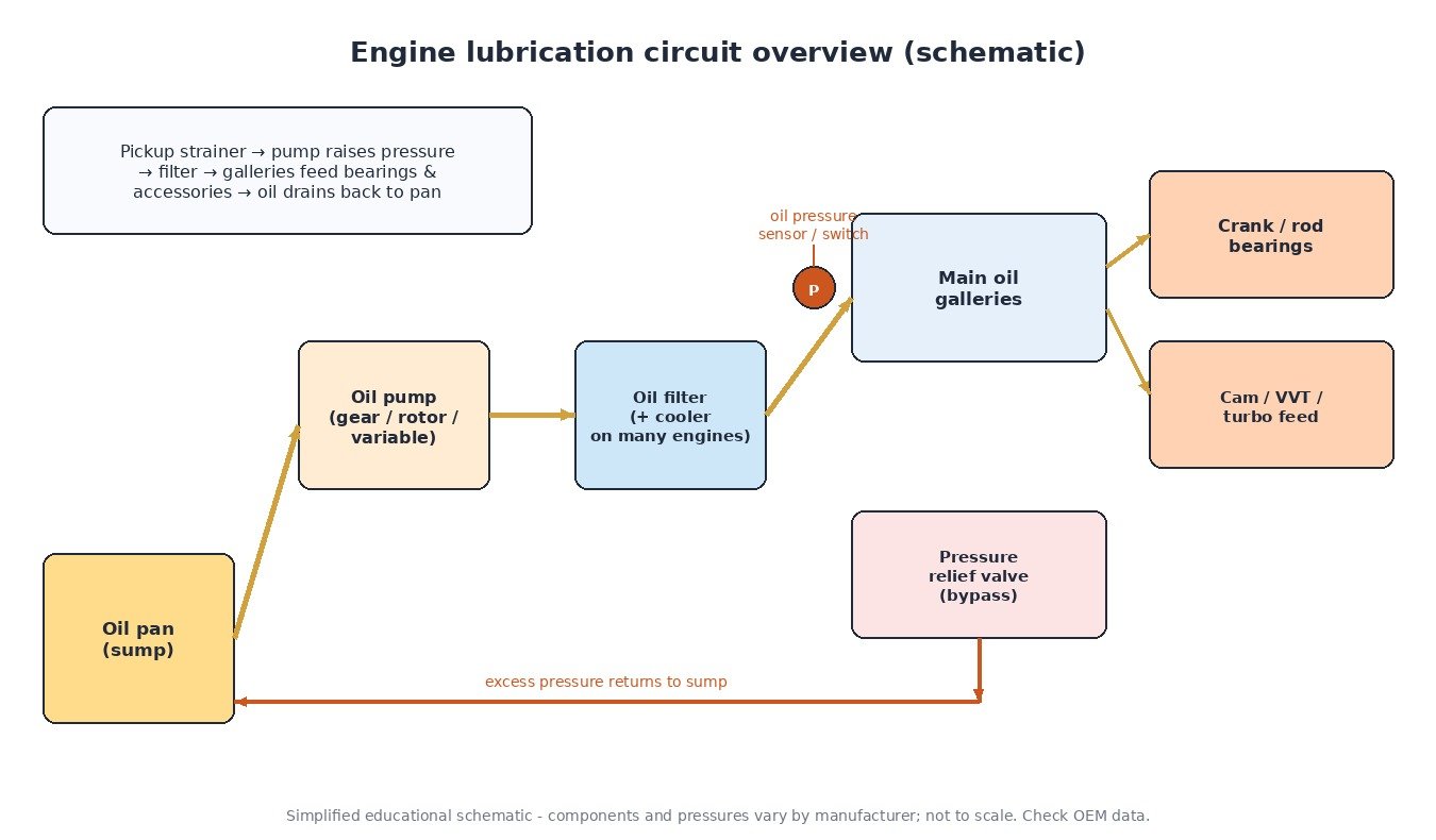
The lubrication loop is straightforward in principle. Oil is drawn from the sump through a pickup strainer into a positive-displacement pump. The pump delivers oil through the filter (and often a cooler) into the main oil galleries. Branches feed the crankshaft main bearings, connecting-rod bearings, camshafts, hydraulic lash adjusters or VVT phasers, and frequently a turbocharger. Oil then drains back to the pan by gravity.
Pressure is limited by a relief valve: when delivery exceeds demand — classic cold-start with viscous oil, or high pump speed — the valve opens and returns oil to the sump or pump inlet. Exact idle and peak pressures are engine-specific and depend on oil grade and temperature; do not rely on generic bar or psi figures from memory. Use the OEM specification for that engine family.
Switch or transducer?
An oil pressure switch is a threshold device. Above a designed pressure the contacts change state; below it they change back. Many older cars, small diesels and motorcycles still wire that switch straight to the oil warning lamp, with or without an ECU digital input. You cannot graph pressure — only detect a binary fault.
An analog pressure transducer measures continuously. The sensing element (often piezoresistive) produces a voltage proportional to gallery pressure, which the ECU digitizes. That continuous value supports map-based monitoring (pressure versus rpm and oil temperature), closed-loop control of a variable oil pump, and separate DTCs for circuit faults versus genuinely low pressure. On CAN-based senders the principle is the same: the ECU still receives a live pressure value, not just a lamp request.
ECU reactions and variable pumps
With a valid pressure reading the ECU typically:
- Illuminates a warning when pressure falls below the allowed band for the current speed and temperature.
- Applies a torque or fuel derate (limp behaviour) if low pressure persists, protecting the crankshaft and rod bearings.
- On engines with a variable-displacement oil pump, commands a target pressure and modulates the pump actuator (often PWM) so the measured pressure tracks the target — lower pressure at light load saves fuel; higher pressure at high load protects the hardware.
- Runs plausibility checks against expected pressure for rpm, load and oil temperature, setting range/performance codes when the story does not add up.
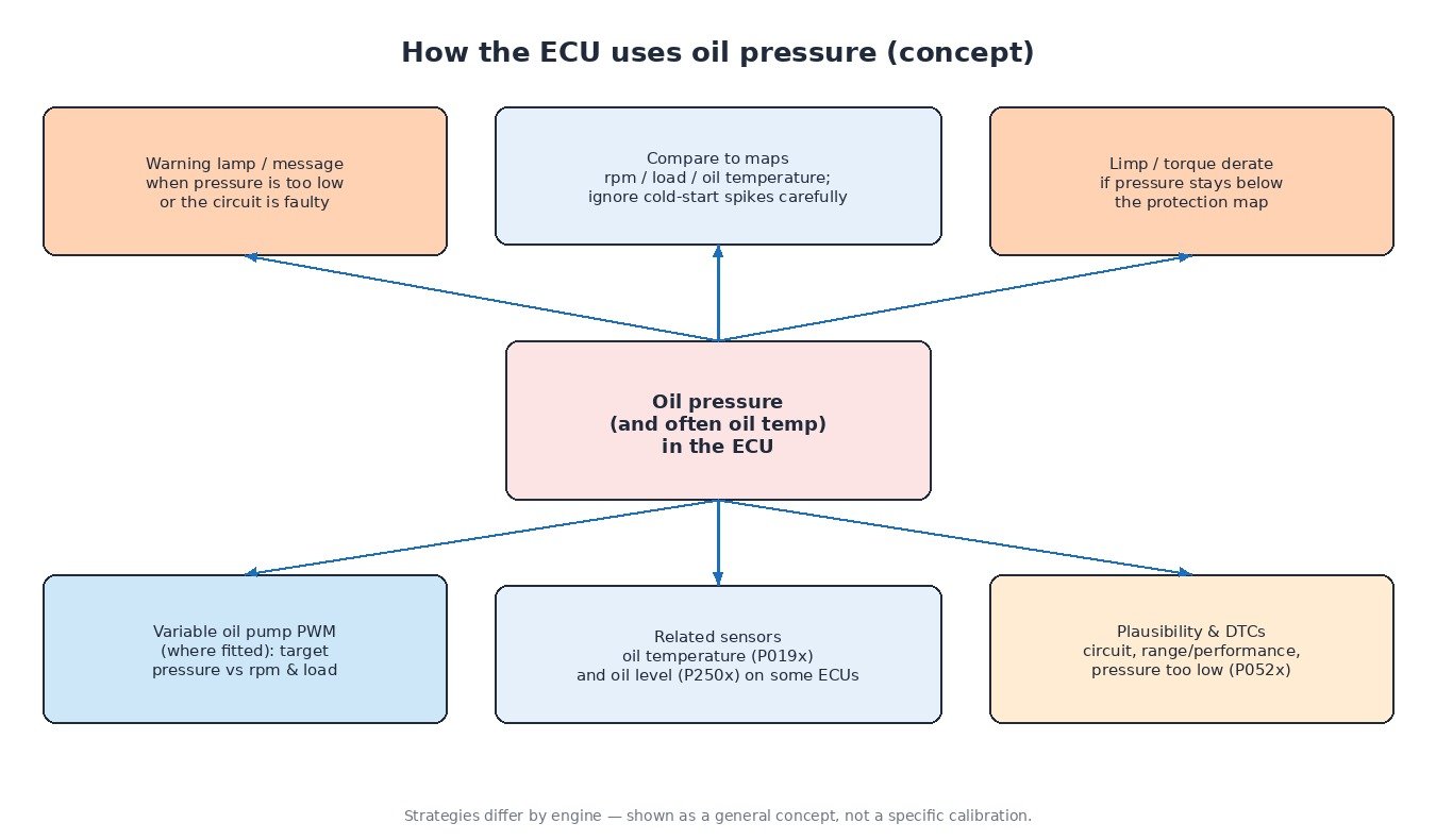
Oil temperature sensors (P0195–P0198) and, on some applications, oil level sensors (P250A/P250B) sit beside this logic. Viscosity — and therefore pressure — tracks temperature; a empty or near-empty sump precedes a pressure collapse. Diagnose them as related systems.
Diagnostic routine for P052x
- Capture context. Note whether the lamp or code appears only at hot idle, under boost, or always. Freeze-frame rpm and temperatures matter.
- Verify real gallery pressure. Fit a mechanical gauge at the specified test port. If mechanical pressure is healthy but the scan PID is wrong, focus on the sensor and wiring. If both are low, hunt mechanical causes: level, wrong viscosity, worn pump, stuck-open relief, clogged pickup, or internal leakage.
- Circuit path for P0520 / P0522 / P0523. Check reference, signal and ground. Opens read high; shorts to ground read low. Inspect for oil intrusion in the connector and abrasion against the block or timing cover.
- P0521 and P0524. Range/performance often means a slow or biased sensor, incorrect oil, or a relief valve that chatters. P0524 is the ECU stating pressure is actually too low for protection maps — treat it as a mechanical urgency until proven otherwise.
- Variable pump bi-directional tests. Where the tool allows, raise and lower commanded pressure and confirm the gallery follows. A pump that ignores commands is not fixed by a new sensor.
Across vehicle types
Modern passenger cars and vans lean toward transducers and mapped pump control. Trucks and agricultural diesels move large oil volumes through long galleries and turbo feeds; sustained high-load pressure drop under field or haulage work deserves immediate mechanical attention. Tractors under PTO load run hot oil for long periods, so protection derates are common when the lubrication system is marginal. Bikes often keep a simple switch and lamp; larger engines may add a gauge sender. Always pull the wiring diagram and pressure table for the exact model year.
Related fault codes (DTCs)
SAE J2012 generic definitions. Confirm OEM wording and thresholds before replacing parts.
| Code | Meaning | Typical causes |
|---|---|---|
| P0520 | Engine Oil Pressure Sensor/Switch Circuit | Harness open/short, failed sensor or switch, poor connector |
| P0521 | Engine Oil Pressure Sensor/Switch Range/Performance | Biased sensor, incorrect oil, relief valve, implausible vs operating point |
| P0522 | Engine Oil Pressure Sensor/Switch Low | Signal short to ground, failed sender |
| P0523 | Engine Oil Pressure Sensor/Switch High | Open signal circuit, unplugged sensor, short to voltage |
| P0524 | Engine Oil Pressure Too Low | Low level, weak pump, relief stuck open, blocked pickup, internal leak |
| P0195 | Engine Oil Temperature Sensor Circuit | Oil temperature sensor or wiring |
| P0196 | Engine Oil Temperature Sensor Range/Performance | Drifting oil temp sensor, implausible after cold soak |
| P0197 | Engine Oil Temperature Sensor Low | Low signal / short to ground |
| P0198 | Engine Oil Temperature Sensor High | Open circuit or high signal |
| P250A | Engine Oil Level Sensor Circuit | Level sensor circuit fault |
| P250B | Engine Oil Level Sensor Circuit Range/Performance | Implausible level, contaminated or failing sensor |
Tuning implications
Higher torque increases bearing load and oil shear. Keep oil-pressure monitoring and any factory derate active in the calibration. Do not raise variable-pump “efficiency” maps so far that gallery pressure collapses at peak load. Clear lubrication and sensor faults before delivering a Stage 1 or Stage 2 file, and prefer logging the oil-pressure PID on a loaded road or dyno run afterwards — especially on engines that tow, climb or drive implements for long stretches.
Need a calibration that keeps oil-pressure protection intact? Browse tuning files at ECUFlashFiles.