
Ask an ECU how much air the engine is taking in and, on a huge number of petrol cars, turbo diesels, trucks and motorcycles, the answer starts with one input: manifold pressure. This guide walks through the MAP and boost pressure sensor from the workshop side — what it actually measures, how the ECU turns pressure into load, how it closes the loop on boost, how to diagnose it, and what a calibrator needs to respect.
Why the ECU wants absolute pressure
A boost gauge in the cabin shows gauge pressure: zero is whatever the atmosphere happens to be. The ECU works in absolute pressure, where zero is a vacuum. The two differ by the barometric pressure: absolute = gauge + BARO. Standard sea-level atmosphere is about 101 kPa, and it falls as you climb.
The reason is physics. The mass of air trapped in a cylinder depends on absolute pressure and temperature, not on how far above ambient the turbo is pushing. Working in absolute values lets one calibration behave the same on a coastal motorway and a mountain pass.
Inside the sensor: silicon, strain and a vacuum reference
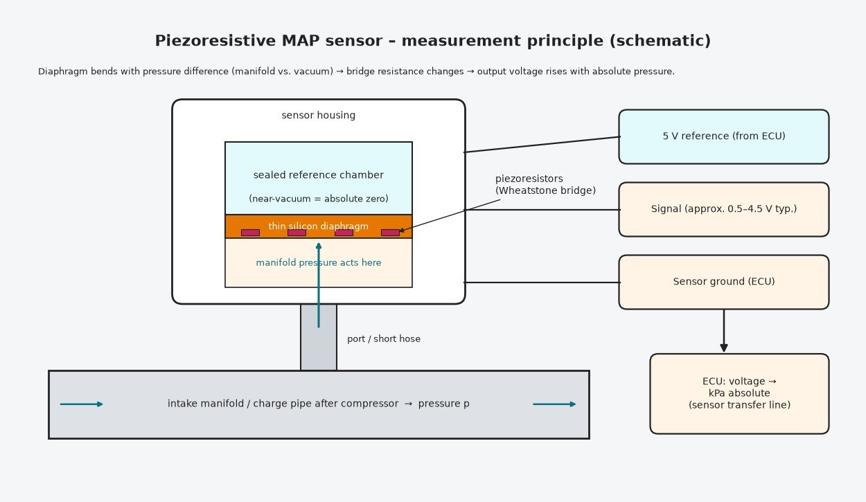
The sensing element is a silicon die with a thinned section acting as a diaphragm. One side faces a sealed cavity pumped to near-vacuum during manufacture. The other side sees manifold or charge-air pressure through a port. As pressure rises the diaphragm deflects further.
Resistors formed in the silicon change value when stretched or compressed — the piezoresistive effect. Arranged as a Wheatstone bridge, they convert deflection into a small voltage that integrated electronics amplify and temperature-correct.
Signal and supply
- 5 V reference from the ECU
- Sensor ground returned to the ECU, not to the chassis
- Signal, ratiometric to the reference, usually kept inside roughly 0.5–4.5 V so shorts and open circuits fall outside the valid band
- On a TMAP, an extra wire for the integrated air-temperature sensor
Sensors are made in different ranges (1, 2.5 and 3 bar absolute are typical). The ECU converts voltage into kPa using an offset and gradient that must match the fitted part.
Locations on cars, vans, trucks and bikes
A naturally aspirated petrol engine measures the plenum, downstream of the throttle. A turbo engine reads charge pressure after the intercooler; some layouts add a second sensor before the throttle so the ECU knows both boost and manifold pressure. Light vans and heavy trucks with diesel engines nearly always have a charge-air sensor, often as a TMAP on the intake manifold, even when a MAF is also fitted. Tractors and other off-road diesels use the same principle for boost control and smoke limiting.
Many motorcycles, scooters and small engines use MAP alone. On single-cylinder engines the ECU reads pressure at a fixed crank position because the signal swings with every intake stroke.
BARO versus MAP
BARO is ambient pressure. It may come from a sensor on the ECU circuit board, a separate sensor, or a reading taken from the MAP sensor at key-on before cranking. The ECU uses BARO for altitude corrections — air charge, fuel, ignition and especially turbo protection — and as a reference to check the MAP sensor. With the engine stopped, both sensors are measuring the same atmosphere and should agree closely; if they do not, P0069 is the classic result.
Speed-density load calculation
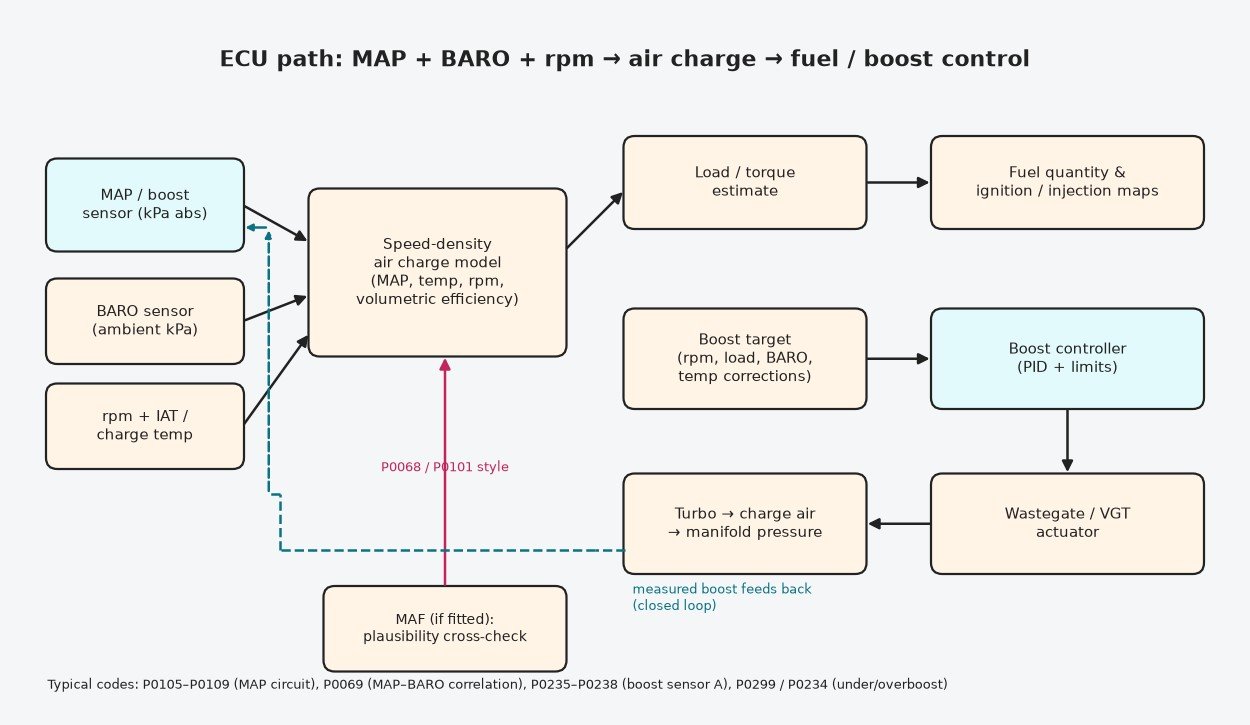
When an engine has no MAF, or as a parallel model when it does, the ECU estimates air charge from speed and density: rpm, manifold pressure and intake temperature. Using the gas law with known displacement, it calculates how much air the cylinder could hold at those conditions, then corrects it with a volumetric efficiency table that describes how well the engine really fills at each rpm and pressure. Cam phasing, intake runner flaps and exhaust back-pressure all influence that table.
The air charge drives fuel quantity and ignition, and becomes the load axis for many other maps. Where a MAF is present the ECU continually compares the two estimates; a sustained mismatch hints at a leak or a sensor error and on many platforms triggers P0068 or a MAF range code.
Closing the loop on boost
For a turbocharged engine the pressure sensor is the controller’s eyes. The ECU calculates a boost target from requested torque, rpm, BARO and temperatures, then adjusts the wastegate or VGT actuator to hold it. Feed-forward maps get close; the closed-loop part trims the rest. Persistent error raises P0299 (underboost) or P0234 (overboost) and typically triggers limp mode. On diesels the same signal feeds the smoke limiter that caps injected fuel until enough air has arrived — important on trucks and tractors that spend long periods at full load.

Diagnosing MAP and boost sensor faults
Typical root causes
- Cracked, soft or disconnected sensor hose, or a blocked sensor port
- Oil and soot build-up from crankcase ventilation and EGR — very common on diesel TMAPs
- Charge-air leaks at intercooler hoses and clamps
- A shared 5 V reference pulled low by a different shorted sensor
- Corroded pins and chafed wiring near the turbo or exhaust
Workshop sequence
- Read codes and freeze frame; note whether the fault is circuit (low/high), range/performance or correlation.
- Key on, engine off: compare MAP with BARO. They should match closely.
- Run the engine: idle should show clear vacuum on a petrol engine; the reading must respond instantly to throttle changes. A frozen value points to a blocked port or failed element.
- Check 5 V reference, ground and signal at the connector. Unplug other sensors on the same reference to find a short.
- Bench-test with a hand pump: the voltage should change smoothly with pressure.
- Smoke- or pressure-test the intake and charge-air path before condemning the turbo or the sensor.
Related fault codes (DTCs)
Generic OBD-II (SAE J2012) codes related to manifold absolute pressure and barometric pressure sensing, turbo/supercharger boost sensors, MAP/BARO and MAP/MAF/throttle correlation, and the boost deviation codes a faulty pressure signal can trigger. Exact wording and enable conditions vary by manufacturer.
| Code | Meaning | Typical causes |
|---|---|---|
| P0068 | MAP/MAF – Throttle Position Correlation | MAP, MAF and throttle position disagree: intake/charge-air leak, sticking throttle, contaminated MAF, faulty or blocked MAP sensor |
| P0069 | Manifold Absolute Pressure – Barometric Pressure Correlation | MAP and BARO readings differ with engine stopped or at low load: drifting MAP or BARO sensor, blocked or wet sensor port, wiring/5 V reference fault |
| P0105 | Manifold Absolute Pressure/Barometric Pressure Circuit | Open or short in MAP signal, 5 V reference or ground circuit, unplugged connector, failed sensor |
| P0106 | Manifold Absolute Pressure/Barometric Pressure Circuit Range/Performance | Reading implausible for rpm/throttle/load: split or disconnected sensor hose, oily or sooted sensor, intake or charge-air leak, sensor drift |
| P0107 | Manifold Absolute Pressure/Barometric Pressure Circuit Low | Signal or 5 V reference open/shorted to ground, shared 5 V reference pulled down by another sensor, failed sensor |
| P0108 | Manifold Absolute Pressure/Barometric Pressure Circuit High | Signal shorted to voltage, open sensor ground, failed sensor; on some engines a real overpressure event |
| P0109 | Manifold Absolute Pressure/Barometric Pressure Circuit Intermittent | Loose or corroded connector pins, chafed harness, intermittent ground |
| P0234 | Turbocharger/Supercharger "A" Overboost Condition | Wastegate or VGT stuck/slow, boost control valve or vacuum fault, boost sensor reading low or wrong, aggressive calibration |
| P0235 | Turbocharger/Supercharger Boost Sensor "A" Circuit | Boost pressure sensor or wiring fault, unplugged connector, 5 V reference problem |
| P0236 | Turbocharger/Supercharger Boost Sensor "A" Circuit Range/Performance | Boost reading implausible vs BARO or target: oily or blocked sensor, charge-air leak, sensor drift |
| P0237 | Turbocharger/Supercharger Boost Sensor "A" Circuit Low | Signal open or shorted to ground, 5 V reference low, failed sensor |
| P0238 | Turbocharger/Supercharger Boost Sensor "A" Circuit High | Signal shorted to voltage, open ground, failed sensor |
| P0239 | Turbocharger/Supercharger Boost Sensor "B" Circuit | Second boost sensor (twin-turbo / bi-turbo layouts) or wiring fault |
| P0240 | Turbocharger/Supercharger Boost Sensor "B" Circuit Range/Performance | Implausible reading from boost sensor B: leak, contamination, sensor drift |
| P0241 | Turbocharger/Supercharger Boost Sensor "B" Circuit Low | Sensor B signal open or shorted to ground, failed sensor |
| P0242 | Turbocharger/Supercharger Boost Sensor "B" Circuit High | Sensor B signal shorted to voltage, open ground, failed sensor |
| P0299 | Turbocharger/Supercharger "A" Underboost Condition | Charge-air leak (hose, intercooler, clamp), wastegate/VGT stuck open, actuator or vacuum fault, restricted intake or exhaust, worn turbo, boost sensor reading high |
| P2226 | Barometric Pressure Sensor "A" Circuit | BARO sensor (often inside the ECU or combined with another sensor) or wiring fault |
| P2227 | Barometric Pressure Sensor "A" Circuit Range/Performance | BARO reading implausible vs MAP at key-on: BARO or MAP sensor drift, internal ECU sensor fault |
| P2228 | Barometric Pressure Sensor "A" Circuit Low | BARO signal open or shorted to ground, failed sensor |
| P2229 | Barometric Pressure Sensor "A" Circuit High | BARO signal shorted to voltage, open ground, failed sensor |
| P2230 | Barometric Pressure Sensor "A" Circuit Intermittent/Erratic | Loose connection or failing BARO sensor |
Calibration and tuning considerations
A tune that raises boost must stay inside the sensor’s measuring range; once the signal saturates, the ECU cannot see real pressure and boost control becomes unreliable. Fitting a higher-range sensor is common on modified engines, but its linearisation in the file must be updated to match, along with every limit expressed in pressure. Speed-density engines need their VE data re-checked from logs after intake, cam or turbo changes. Keep overboost protection, BARO-based altitude correction and turbo-speed limits active and sensibly set. Use the sensor data and definition for the actual ECU — never copy numeric values from a generic article.
Summary
The MAP or boost sensor measures absolute pressure with a piezoresistive silicon diaphragm and a vacuum reference. The ECU combines it with BARO, temperature and rpm to calculate air charge and to control boost. Most problems are hoses, contamination, leaks and wiring rather than a failed sensor, so compare key-on MAP with BARO, log the reading under load and leak-test before replacing parts. In calibration, the sensor’s range and scaling define everything built on top of it.
Need files that work with your boost and load sensors? Browse tuning files at ECUFlashFiles.