
When a car or van runs lean, smokes oddly after a remap, or stores P0101 under load, the mass air flow sensor is high on the suspect list — but it is not always the failed part. This workshop-oriented guide covers how hot-film and hot-wire MAF sensors measure air mass, how the ECU turns that into load and fueling, how to separate contamination and post-MAF leaks from wiring faults, and what tuners must respect in the air-mass path.
Air mass, not just volume
Combustion cares about oxygen mass, not litres of air. Temperature and pressure change density, so a pure volume meter would mislead the ECU outside a narrow operating point. A MAF reports mass flow, usually in g/s on the scan tool. That value drives petrol injector pulsewidth calculations and, on many diesels that still fit a MAF, smoke and air-path limiters.
Engines without a MAF — including most motorcycles and many heavy-duty diesels — infer air mass from MAP, rpm and a volumetric-efficiency model (speed-density). Cars and light vans that keep a MAF gain a direct measurement in the intake tract; trucks that use a MAF follow the same electrical and contamination issues described below.
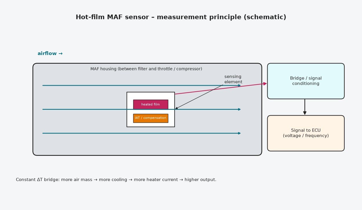
Hot-film and hot-wire sensors in practice
Both families are thermal anemometers. A heated element sits in the airflow; more mass flow removes more heat; the electronics measure the power needed to hold a set temperature (or the temperature change at fixed power).
Hot-wire
A fine platinum wire was the original production approach. Constant-temperature bridges adjust heater current so the wire stays at a fixed temperature above the air. The current (and the voltage derived from it) rises with mass flow. The wire is delicate and fouls easily, so passenger-car designs largely moved on.
Hot-film (HFM)
Modern housings use a hot-film chip: thin-film heaters and temperature sensors on a substrate. Part of the chip measures incoming air temperature; another is heated and held at a controlled temperature difference by a bridge. Output may be analogue voltage, frequency, or a digital message. The ECU applies a calibrated transfer curve to turn that into air mass. IAT is frequently built into the same unit, which matters when you see MAF and IAT codes together.
Intake placement and the integrated IAT
Mount the mental model correctly: filter → MAF → (turbo compressor on many engines) → intercooler/throttle → manifold. Everything the engine breathes should pass the sensing element. A leak after the MAF adds oxygen the ECU did not count. Oil vapour from the PCV system or an over-oiled catch can coats the film and typically makes the reading low for the real flow.
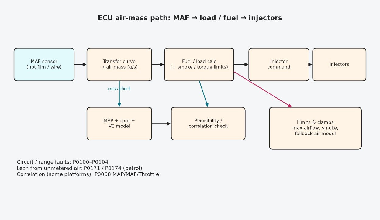
From grams per second to fuel and load
On MAF-based petrols, air mass is the backbone of the base fuel calculation and of calculated engine load. Closed-loop fuel trims then fine-tune around the oxygen sensor feedback. The ECU often runs a parallel MAP-based air estimate and compares the two; large, lasting disagreement can set a correlation code such as P0068 or drop the system into a limp air model.
On MAF-equipped diesels, injection quantity may be commanded mainly from torque demand, but air mass still caps smoke and shapes EGR and boost-related models. If the MAF under-reads, those limiters can activate early and the vehicle feels soft even when the torque maps look bold.
Why MAF readings go wrong
- Dirty or oily film — under-reading, hesitation, rich smell or early smoke limiting depending on strategy.
- Unmetered air after the sensor — lean bank codes (P0171 / P0174), high positive fuel trims, whistle or hiss on a smoke test.
- Electrical faults — open/shorted signal, bad 5 V reference, corroded pins → P0100 / P0102 / P0103 / P0104.
- Plausibility failures — signal present but inconsistent with rpm, MAP or throttle → P0101 range/performance.
- Wrong sensor or skewed curve — aftermarket or incorrect OE substitute that does not match the ECU transfer.
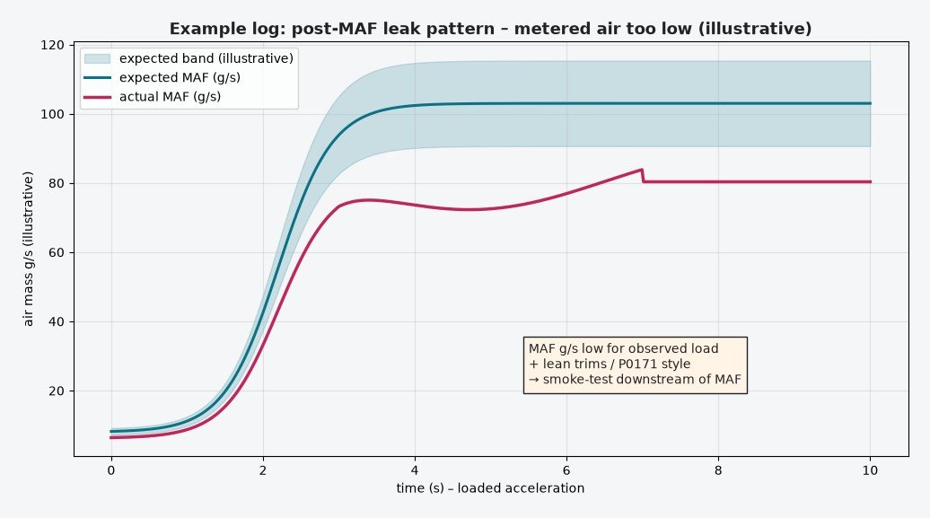
Diagnosing P0100–P0104 in the bay
- Capture freeze frame: rpm, load, MAF g/s, MAP, fuel trims, IAT.
- Graph MAF during a controlled pull. Expect a smooth rise with load; a flat, spiky or wildly low trace is more useful than a static idle number alone.
- If trims are lean and MAF looks low for the power the vehicle makes, smoke-test the intake downstream of the MAF before replacing the sensor.
- If circuit codes are set, verify supply, ground and signal at the connector under load (wiggle test for P0104).
- When IAT codes share the housing, fix the connector and reference first — one bad ground can look like two failed sensors.
Compare MAF-derived air mass with a MAP × VE estimate where you have the data. Agreement under steady cruise and disagreement only at high load often points to a clamp, a skewed transfer, or a leak that opens under boost or vacuum.
Related fault codes (DTCs)
Generic OBD-II (SAE J2012) codes related to mass air flow sensing, the integrated intake air temperature sensor often built into the MAF housing, lean mixture from unmetered air, and MAP/MAF/throttle correlation. Exact wording and enable conditions vary by manufacturer.
| Code | Meaning | Typical causes |
|---|---|---|
| P0100 | Mass or Volume Air Flow "A" Circuit | Open/short in MAF signal circuit, unplugged connector, failed sensor, wiring damage |
| P0101 | Mass or Volume Air Flow "A" Circuit Range/Performance | MAF reading implausible vs rpm/MAP/throttle: contaminated film, intake leak after MAF, skewed transfer curve, wrong sensor |
| P0102 | Mass or Volume Air Flow "A" Circuit Low | Signal open or shorted to ground, failed sensor, poor ground, severe contamination causing very low output |
| P0103 | Mass or Volume Air Flow "A" Circuit High | Signal shorted to voltage, open ground, failed sensor |
| P0104 | Mass or Volume Air Flow "A" Circuit Intermittent | Loose connector pins, chafed harness, intermittent supply or ground |
| P0110 | Intake Air Temperature Sensor "A" Circuit | IAT circuit fault (often integrated in the MAF housing): open/short, failed element, shared connector issue |
| P0111 | Intake Air Temperature Sensor "A" Circuit Range/Performance | IAT reading implausible vs ECT/ambient after soak, contaminated or failed IAT element in MAF housing |
| P0112 | Intake Air Temperature Sensor "A" Circuit Low | IAT signal shorted to ground or failed low |
| P0113 | Intake Air Temperature Sensor "A" Circuit High | IAT signal open or shorted to voltage (common when MAF/IAT connector is unplugged) |
| P0114 | Intake Air Temperature Sensor "A" Circuit Intermittent | Loose pins or damaged harness at the MAF/IAT connector |
| P0171 | System Too Lean (Bank 1) | Unmetered air after the MAF (intake leak), low fuel pressure, exhaust leak before O2 sensor, contaminated MAF under-reading |
| P0174 | System Too Lean (Bank 2) | Same lean causes on bank 2: post-MAF leak, fuel delivery, or MAF under-read on V-engines |
| P0068 | MAP/MAF – Throttle Position Correlation | MAF, MAP and throttle disagree: post-MAF leak, contaminated or failed MAF, MAP fault, throttle body / TPS issue |
MAF scaling and calibration limits
Remaps that add fuel or torque must stay consistent with measured air mass and with any maximum airflow clamps in the ECU. Ignoring those clamps can trigger P0101-style plausibility faults or force the controller onto a fallback model. Scaling the MAF to “make room” for more fuel without matching hardware and logging is a common way to create lean or rich problems that only appear on the road.
After calibration changes, log MAF g/s against MAP and rpm on a full-load run. Confirm the sensor is not stuck against a software ceiling and that smoke or fuel limiters behave as intended. Use the vehicle’s own definition file and measured data — do not copy numeric axis values from a generic article.
Summary
Hot-film and hot-wire MAF sensors infer air mass from cooling of a heated element. The ECU uses that mass for fueling, load and limiters, and often cross-checks it with MAP. In the workshop, separate contamination and post-MAF leaks from true circuit faults using live g/s, smoke testing and basic electrical checks. For tuning, keep MAF scaling and airflow clamps aligned with reality so the file and the sensor tell the same story.
Need files that work with your MAF and fuel maps? Browse tuning files at ECUFlashFiles.