
If the engine management system had to name its most-used feedback signal on a petrol car, it would be the oxygen sensor. Mounted in the exhaust, the lambda or O2 sensor reports what actually came out of combustion, and the ECU corrects fueling from it continuously. This guide covers narrowband and wideband designs, sensor positions, fuel trims, typical failures and a workshop routine for diagnosis — for cars, vans, trucks and bikes.
Why the ECU needs an oxygen signal
Fueling starts as a calculation: measured or estimated air mass, divided by a target air-fuel ratio, gives the fuel quantity to inject. Real engines drift as injectors wear and leaks appear, so the ECU checks the result by measuring leftover oxygen in the exhaust.
The result is expressed as lambda (λ), the ratio of actual to stoichiometric air-fuel ratio. Stoichiometric for petrol is roughly 14.7 parts air to 1 part fuel by mass, which is λ = 1. Below 1 is rich, above 1 is lean. Because lambda is relative, it means the same thing on petrol, ethanol blends, LPG or diesel, even though their stoichiometric AFRs differ. Three-way catalysts work best in a tight band around λ = 1.
Narrowband sensors: a fast rich/lean switch
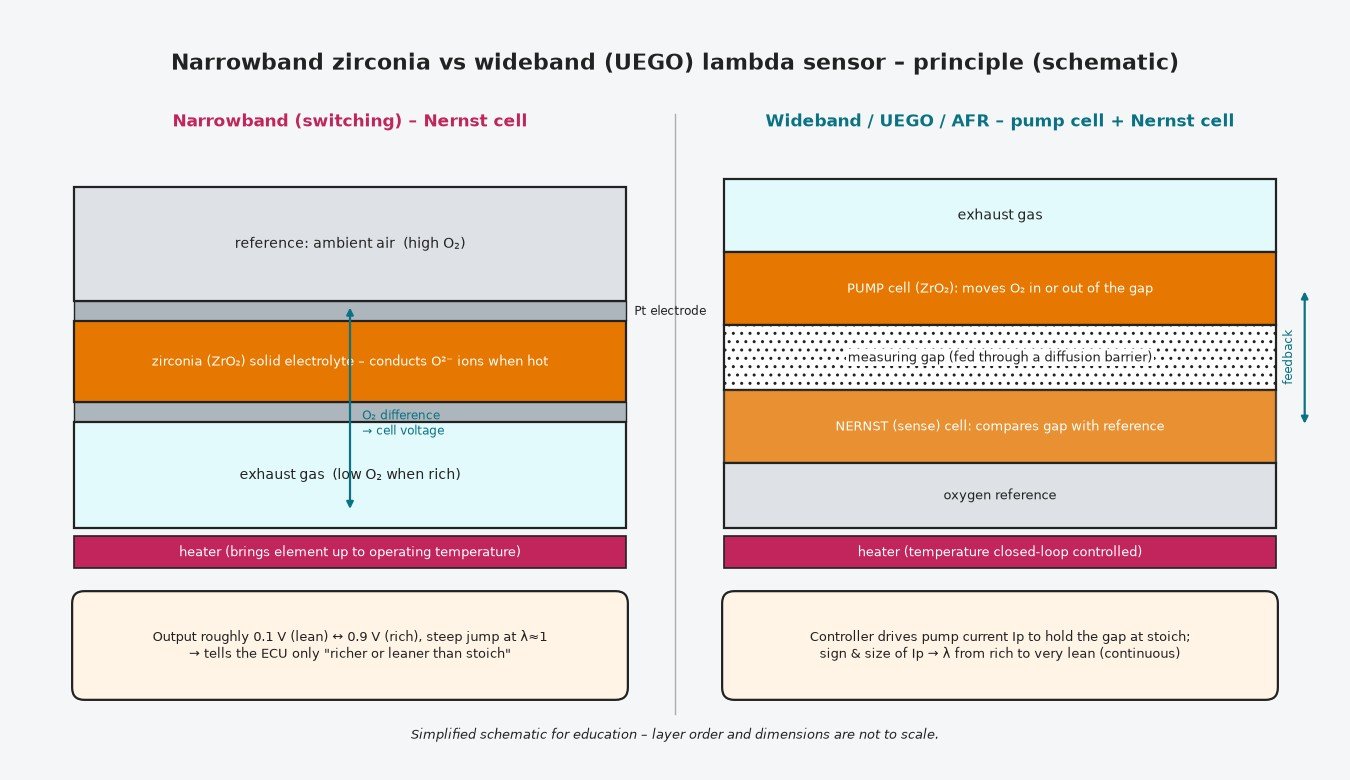
A narrowband (switching) sensor is a zirconia element with platinum electrodes — one face in the exhaust, the other exposed to a reference, typically outside air. Hot zirconia lets oxygen ions move through it, and the difference in oxygen between the two faces generates a voltage, the Nernst effect.
- Rich exhaust (almost no free oxygen): output about 0.8–0.9 V.
- Lean exhaust (spare oxygen): output about 0.1 V.
- Around λ = 1 the voltage jumps sharply between the two.
So the sensor tells the ECU which side of stoichiometric the engine is on, not by how much. An integrated heater brings the element to working temperature quickly after start-up and keeps it there at idle and low load; without it the sensor stays inactive and the ECU cannot close the loop.
Wideband sensors: measuring how rich or lean
A wideband sensor (UEGO, “A/F sensor” or LSU-style) uses two zirconia cells. Exhaust reaches a small measuring gap through a diffusion barrier. A sense (Nernst) cell watches the gap, and a pump cell moves oxygen into or out of it until the sense cell sits at a fixed reference — commonly around 0.45 V, the stoichiometric point.
The pump current required is the output: one direction for rich, the other for lean, with magnitude proportional to the deviation. That gives a continuous, linear-like reading over a wide range, which is why widebands appear as upstream sensors on many current petrol engines, on diesels and in every serious logging kit. They need a controller, precise heater regulation and typically five or six wires.
Scan tools present wideband data in different ways — as lambda, as AFR, as current or as a manufacturer-scaled voltage. Never read a wideband voltage as if it were a narrowband.
Sensor 1 vs sensor 2: positions and jobs
Codes and live data refer to bank and sensor. Bank 1 is the cylinder bank with cylinder 1; on inline engines there is only bank 1. Sensor 1 is before the catalyst, sensor 2 after it.
Upstream (pre-cat)
Controls fueling. It sees raw exhaust and switches or moves with every correction.
Downstream (post-cat)
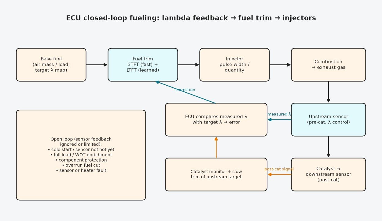
Monitors the catalyst. A working catalyst buffers oxygen, so the rear signal is calm. When oxygen storage fades, the rear signal starts to follow the front one and the efficiency monitor can flag P0420 or P0430. Many systems also use the rear sensor to fine-adjust the front sensor’s target.
Closed-loop fuel trim, step by step
- The ECU computes base fuel from load and the target lambda map.
- The upstream sensor reports measured lambda.
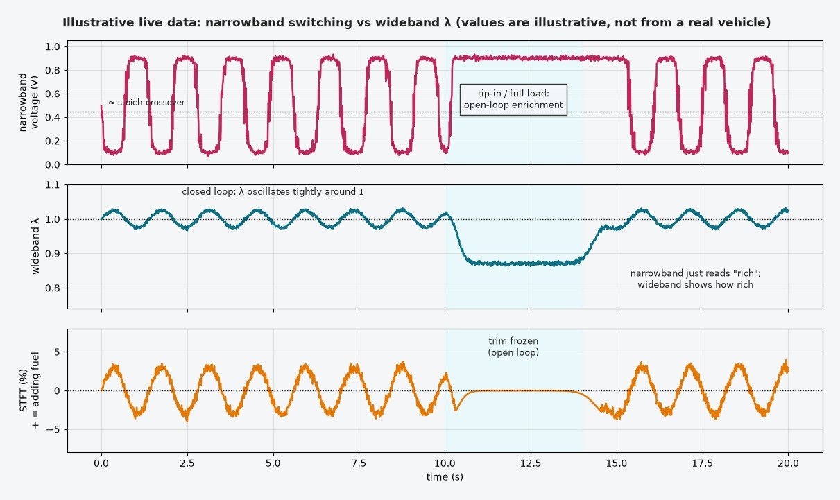
- Short-term fuel trim (STFT) adjusts fuel immediately to remove the error. With a narrowband, this produces a steady rich-lean oscillation around stoichiometric.
- Long-term fuel trim (LTFT) averages STFT and stores it per load or rpm zone, so the base calculation is corrected for that engine’s ageing and tolerances.
- If trims hit their limits, the ECU sets a system lean or rich code (P0171/P0172, P0174/P0175).
Open-loop situations
Lambda feedback is suspended or restricted during cold start before the sensor is ready, under full-load enrichment for component protection, on overrun fuel cut, and after sensor or heater faults. Fueling then comes only from calibrated tables.
Typical failures and false readings
- Heater circuit: open element, fuse, supply or ECU driver fault — slow or no activity and heater codes.
- Poisoned element: silicone vapour from unsuitable RTV sealants, coolant, burnt oil or fuel additives deposit on the tip and slow or bias the response.
- Exhaust leaks upstream of the sensor: air pulled in through a leak adds oxygen, so the sensor reports lean. The ECU adds fuel and the engine actually runs rich — a classic false lean.
- Wiring: chafing on hot exhaust parts, corroded pins, water in connectors, broken reference or ground circuits.
- Genuine mixture faults: intake leaks, weak fuel supply, dirty injectors or a wrong air-mass signal. Replacing the sensor will not help.
A diagnostic routine that saves parts
- Note the exact code type: circuit, heater, slow/delayed response, or biased/stuck.
- Measure heater resistance cold and compare with service data; confirm supply, fuse and ECU control.
- Warm the engine fully and confirm closed loop in live data. Check that the sensor responds to a quick throttle blip and to a brief rich and lean change.
- Compare STFT and LTFT at idle and at a steady higher rpm. Idle-only lean trims hint at vacuum leaks; lean at all loads points to fuel or air-mass measurement.
- Check the exhaust for leaks ahead of the sensor and smoke-test the intake.
- Inspect connectors and harness routing. Replace the sensor last, with the correct part for that ECU.
Related fault codes (DTCs)
Generic OBD-II (SAE J2012) codes for oxygen / lambda sensor circuits, heaters and response, plus the fuel-trim and catalyst codes a faulty or misread O2 signal often triggers. Bank 1 is the bank containing cylinder 1; Sensor 1 is upstream (pre-cat), Sensor 2 downstream (post-cat). Exact wording and enable conditions vary by manufacturer.
| Code | Meaning | Typical causes |
|---|---|---|
| P0130 | O2 Sensor Circuit (Bank 1 Sensor 1) | General circuit fault on the upstream (pre-cat) sensor: open/short in signal or reference wiring, damaged connector, failed sensor |
| P0131 | O2 Sensor Circuit Low Voltage (Bank 1 Sensor 1) | Signal shorted to ground or stuck low; on upstream (pre-cat) sensors also a real lean condition such as an exhaust leak ahead of the sensor or unmetered air |
| P0132 | O2 Sensor Circuit High Voltage (Bank 1 Sensor 1) | Signal shorted to voltage (e.g. heater supply), contaminated sensor, or a genuinely rich mixture (leaking injector, high fuel pressure) |
| P0133 | O2 Sensor Circuit Slow Response (Bank 1 Sensor 1) | Aged, contaminated or poisoned sensing element (silicone, oil, coolant), exhaust leak, heater not reaching temperature |
| P0134 | O2 Sensor Circuit No Activity Detected (Bank 1 Sensor 1) | Sensor not switching or reading: cold sensor due to heater fault, open signal circuit, failed element, sensor unplugged |
| P0135 | O2 Sensor Heater Circuit (Bank 1 Sensor 1) | Heater element open (check resistance), blown fuse or no heater supply, damaged wiring/connector, ECU heater driver fault |
| P0136 | O2 Sensor Circuit (Bank 1 Sensor 2) | General circuit fault on the downstream (post-cat) sensor: open/short in signal or reference wiring, damaged connector, failed sensor |
| P0137 | O2 Sensor Circuit Low Voltage (Bank 1 Sensor 2) | Signal shorted to ground or stuck low; on downstream (post-cat) sensors also a real lean condition such as an exhaust leak ahead of the sensor or unmetered air |
| P0138 | O2 Sensor Circuit High Voltage (Bank 1 Sensor 2) | Signal shorted to voltage (e.g. heater supply), contaminated sensor, or a genuinely rich mixture (leaking injector, high fuel pressure) |
| P0139 | O2 Sensor Circuit Slow Response (Bank 1 Sensor 2) | Aged, contaminated or poisoned sensing element (silicone, oil, coolant), exhaust leak, heater not reaching temperature |
| P0140 | O2 Sensor Circuit No Activity Detected (Bank 1 Sensor 2) | Sensor not switching or reading: cold sensor due to heater fault, open signal circuit, failed element, sensor unplugged |
| P0141 | O2 Sensor Heater Circuit (Bank 1 Sensor 2) | Heater element open (check resistance), blown fuse or no heater supply, damaged wiring/connector, ECU heater driver fault |
| P0150 | O2 Sensor Circuit (Bank 2 Sensor 1) | General circuit fault on the upstream (pre-cat) sensor: open/short in signal or reference wiring, damaged connector, failed sensor |
| P0151 | O2 Sensor Circuit Low Voltage (Bank 2 Sensor 1) | Signal shorted to ground or stuck low; on upstream (pre-cat) sensors also a real lean condition such as an exhaust leak ahead of the sensor or unmetered air |
| P0152 | O2 Sensor Circuit High Voltage (Bank 2 Sensor 1) | Signal shorted to voltage (e.g. heater supply), contaminated sensor, or a genuinely rich mixture (leaking injector, high fuel pressure) |
| P0153 | O2 Sensor Circuit Slow Response (Bank 2 Sensor 1) | Aged, contaminated or poisoned sensing element (silicone, oil, coolant), exhaust leak, heater not reaching temperature |
| P0154 | O2 Sensor Circuit No Activity Detected (Bank 2 Sensor 1) | Sensor not switching or reading: cold sensor due to heater fault, open signal circuit, failed element, sensor unplugged |
| P0155 | O2 Sensor Heater Circuit (Bank 2 Sensor 1) | Heater element open (check resistance), blown fuse or no heater supply, damaged wiring/connector, ECU heater driver fault |
| P0156 | O2 Sensor Circuit (Bank 2 Sensor 2) | General circuit fault on the downstream (post-cat) sensor: open/short in signal or reference wiring, damaged connector, failed sensor |
| P0157 | O2 Sensor Circuit Low Voltage (Bank 2 Sensor 2) | Signal shorted to ground or stuck low; on downstream (post-cat) sensors also a real lean condition such as an exhaust leak ahead of the sensor or unmetered air |
| P0158 | O2 Sensor Circuit High Voltage (Bank 2 Sensor 2) | Signal shorted to voltage (e.g. heater supply), contaminated sensor, or a genuinely rich mixture (leaking injector, high fuel pressure) |
| P0159 | O2 Sensor Circuit Slow Response (Bank 2 Sensor 2) | Aged, contaminated or poisoned sensing element (silicone, oil, coolant), exhaust leak, heater not reaching temperature |
| P0160 | O2 Sensor Circuit No Activity Detected (Bank 2 Sensor 2) | Sensor not switching or reading: cold sensor due to heater fault, open signal circuit, failed element, sensor unplugged |
| P0161 | O2 Sensor Heater Circuit (Bank 2 Sensor 2) | Heater element open (check resistance), blown fuse or no heater supply, damaged wiring/connector, ECU heater driver fault |
| P0030 | HO2S Heater Control Circuit (Bank 1 Sensor 1) | Open heater control circuit, failed heater element, fuse or supply fault, connector corrosion/water ingress |
| P0031 | HO2S Heater Control Circuit Low (Bank 1 Sensor 1) | Heater control circuit shorted to ground, low-resistance (shorted) heater element, ECU driver fault |
| P0032 | HO2S Heater Control Circuit High (Bank 1 Sensor 1) | Heater control circuit open or shorted to voltage, open heater element |
| P0036 | HO2S Heater Control Circuit (Bank 1 Sensor 2) | Open heater control circuit on the downstream sensor, failed heater, fuse/supply fault |
| P0037 | HO2S Heater Control Circuit Low (Bank 1 Sensor 2) | Downstream heater control circuit shorted to ground or shorted heater element |
| P0038 | HO2S Heater Control Circuit High (Bank 1 Sensor 2) | Downstream heater control circuit open or shorted to voltage |
| P0050 | HO2S Heater Control Circuit (Bank 2 Sensor 1) | Open heater control circuit, failed heater element, fuse or supply fault (bank 2 upstream) |
| P0051 | HO2S Heater Control Circuit Low (Bank 2 Sensor 1) | Heater control circuit shorted to ground or shorted heater element (bank 2 upstream) |
| P0052 | HO2S Heater Control Circuit High (Bank 2 Sensor 1) | Heater control circuit open or shorted to voltage (bank 2 upstream) |
| P014C | O2 Sensor Slow Response – Rich to Lean (Bank 1 Sensor 1) | Aged or contaminated upstream sensor/AFR sensor, heater problem, exhaust leak; often set by a monitor that briefly modulates fueling and times the response |
| P014D | O2 Sensor Slow Response – Lean to Rich (Bank 1 Sensor 1) | Aged or contaminated upstream sensor, heater problem, exhaust leak, wiring resistance |
| P014E | O2 Sensor Slow Response – Rich to Lean (Bank 2 Sensor 1) | As P014C, on bank 2 |
| P014F | O2 Sensor Slow Response – Lean to Rich (Bank 2 Sensor 1) | As P014D, on bank 2 |
| P015A | O2 Sensor Delayed Response – Rich to Lean (Bank 1 Sensor 1) | Sensor reacts late to a commanded mixture change: aged/poisoned element, heater issue, exhaust leak, injector or fuel delivery problem |
| P015B | O2 Sensor Delayed Response – Lean to Rich (Bank 1 Sensor 1) | As P015A in the lean-to-rich direction |
| P015C | O2 Sensor Delayed Response – Rich to Lean (Bank 2 Sensor 1) | As P015A, on bank 2 |
| P015D | O2 Sensor Delayed Response – Lean to Rich (Bank 2 Sensor 1) | As P015B, on bank 2 |
| P2195 | O2 Sensor Signal Biased/Stuck Lean (Bank 1 Sensor 1) | Exhaust leak before the sensor, intake/vacuum leak, low fuel pressure, sensor bias or wiring fault; compare with fuel trims and downstream sensor |
| P2196 | O2 Sensor Signal Biased/Stuck Rich (Bank 1 Sensor 1) | Leaking injector, high fuel pressure, purge valve stuck open, contaminated sensor, signal shorted to voltage |
| P2197 | O2 Sensor Signal Biased/Stuck Lean (Bank 2 Sensor 1) | As P2195, on bank 2 |
| P2198 | O2 Sensor Signal Biased/Stuck Rich (Bank 2 Sensor 1) | As P2196, on bank 2 |
| P0171 | System Too Lean (Bank 1) | Fuel trims at their lean limit: intake/vacuum leak, MAF under-reading, low fuel pressure or flow, clogged injectors, exhaust leak ahead of the upstream sensor |
| P0172 | System Too Rich (Bank 1) | Fuel trims at their rich limit: leaking injectors, high fuel pressure, MAF over-reading, purge fault, sensor bias |
| P0174 | System Too Lean (Bank 2) | As P0171, on bank 2 |
| P0175 | System Too Rich (Bank 2) | As P0172, on bank 2 |
| P0420 | Catalyst System Efficiency Below Threshold (Bank 1) | Worn or damaged catalyst; also downstream sensor fault, exhaust leak, or upstream misfire/fueling problems that damaged the catalyst |
| P0430 | Catalyst System Efficiency Below Threshold (Bank 2) | As P0420, on bank 2 |
Petrol, diesel, GPF, trucks and bikes
Petrol: closed-loop λ = 1 control for the catalyst; GPF-equipped engines also coordinate lambda with filter regeneration. Diesel cars, vans and trucks operate lean, so they rely on wideband sensors for smoke limitation, EGR strategies and aftertreatment control such as DPF regeneration. Heavy trucks with SCR add NOx sensors, which use related zirconia technology and also report oxygen. These are emissions-control systems, and a proper calibration keeps them working. Motorcycles with fuel injection usually carry narrowband sensors; carburettor bikes generally have none, and secondary-air systems can disturb readings.
Logging and calibration notes
For tuning, log a wideband — a factory narrowband only says “rich” at full load. Locate it where outside air cannot be drawn in, and repair leaks first. Keep catalyst protection, diagnostic monitors and lambda control active; set targets for the actual engine and fuel. Large LTFT after a modification means the air-mass or injector data needs work.
Key points
Narrowband sensors switch at λ = 1; widebands measure lambda through pump current. Sensor 1 steers fuel trims, sensor 2 checks the catalyst. Heaters, wiring, leaks and real mixture faults cause most O2 codes, so diagnose before you replace.
Related reading: Lambda and catalyst monitoring on MED17 and lambda probe fault codes for petrol and diesel engines.
Want a tune built around correct closed-loop fueling? Get your tuning file from ECUFlashFiles.