
High intake air temperature, underboost and a P0127 or P0299 on the scan tool often share one hardware story: the path from the compressor through the intercooler (charge-air cooler) to the manifold. Hot charge air, a leaking pipe or a clogged core will not be fixed by clearing codes. This guide covers how charge-air cooling works, how to spot cooler and charge-pipe faults, why post-intercooler IAT matters, and which generic DTCs to expect.
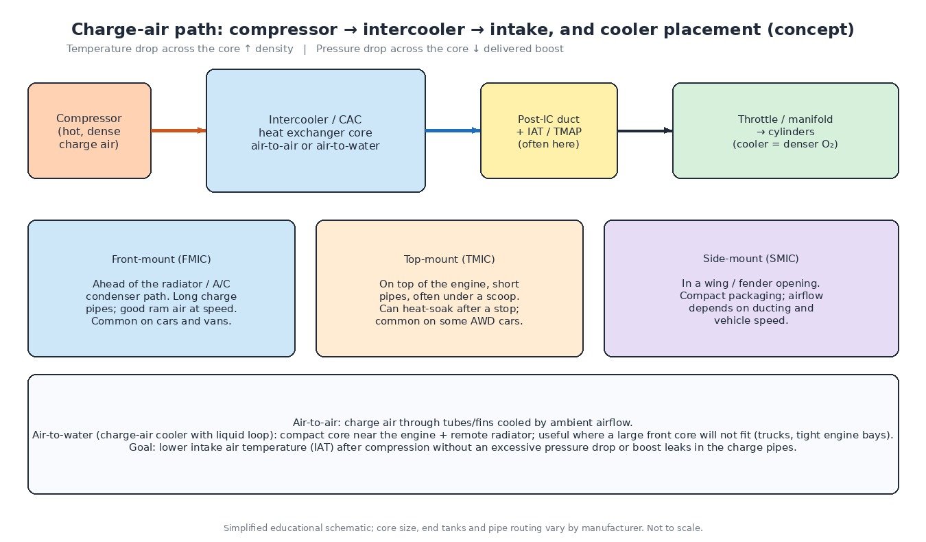
Start with the charge-air path
A turbo or supercharger compresses intake air; that air leaves the compressor hot. The cooler sits between compressor and throttle (or manifold) and rejects heat into ambient airflow or a liquid loop. After the cooler you usually find the duct where many vehicles place an IAT sensor or a combined TMAP (temperature + pressure). If that path leaks, restricts or stops cooling, the ECU sees wrong density, wrong boost and sometimes protection limits — even when the turbo assembly itself is fine.
Cooler types and mounting
Air-to-air cores use fins and tubes cooled by ram air; they dominate cars, vans and many trucks. Air-to-water charge-air coolers use a compact core plus a remote radiator when packaging is tight. Mounting changes the failure pattern:
- Front-mount: best high-speed airflow, longer pipes — more clamps and joints to leak.
- Top-mount: short pipes, heat-soak after a hot shutdown when under-bonnet temperature rises.
- Side-mount: depends on ducting; blocked intakes and crushed ducts raise outlet temperature under load.
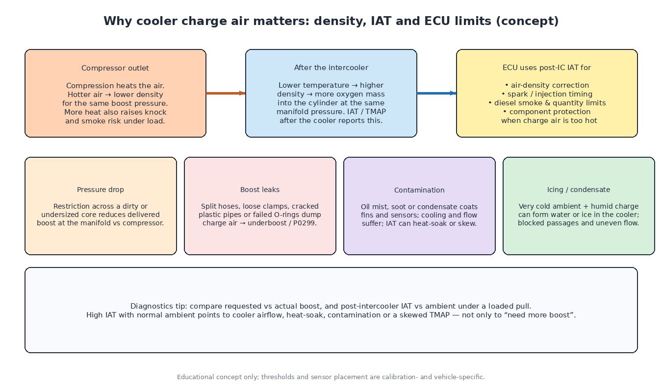
What “good” looks like under load
On a loaded acceleration, post-intercooler IAT should stay well below compressor-outlet temperature when the cooler and airflow are healthy. Ambient IAT (airbox or MAF) will not match post-IC IAT on a boosted pull — that gap is expected. A persistently high post-IC reading with normal ambient points to cooler airflow, fin contamination, heat-soak or a skewed sensor. Also watch pressure drop: if manifold pressure sits far below compressor pressure with no wastegate/VGT reason, suspect a restricted core or a leak between compressor and MAP/TMAP.
Diagnostics: cooler, pipes, then sensor
- Cold soak: key on, engine cold — post-IC IAT should sit close to ambient. A large offset suggests sensor or wiring trouble before you road-test.
- Visual and smoke test: inspect hoses, clamps, plastic pipes and cooler end tanks. Smoke or soapy water under light boost finds leaks that cause P0299 and rough fuelling.
- Log requested vs actual boost and post-IC IAT on the same pull. Underboost with hissing or rapid smoke loss from the pipes is a leak; underboost with high IAT and dirty fins is cooling/restriction.
- Contamination: oil film, soot or dried condensate on the core and IAT element reduce heat transfer and can bias the temperature reading. Clean only as the manufacturer allows; replace damaged sensors.
- Icing / water: after cold humid running, water can pool in the cooler; extreme cold can ice passages. Uneven power and odd IAT behaviour after a cold soak can be physical, not calibration.
- TMAP / IAT circuit: opens often look extremely cold (P0113); shorts to ground often look extremely hot (P0112). Confirm with resistance charts and reference voltage before replacing the cooler.
How the ECU uses post-cooler temperature
Post-IC IAT feeds density correction, timing, diesel smoke/quantity caps and hot-charge protection. That is why P0127 (intake air temperature too high) deserves a hardware check: failed cooler airflow, heat-soaked top-mount packaging, or a sensor stuck high will all trigger protection. Overboost (P0234) and underboost (P0299) belong in the same investigation when charge pipes and the cooler are in the path between compressor and boost sensor. MAP/baro correlation (P0069) and baro circuit codes (P2226–P2229) matter when key-on pressures disagree and the ECU cannot trust altitude or boost plausibility.

Vehicle-type notes
Cars and light vans: charge-pipe clamps and cracked plastic ducts are everyday finds. Trucks and buses: large CACs and long pipes — check chassis-mounted joints after body work. Tractors: dusty fins and chaff screens; high IAT under load often means a cleaning job. Turbo bikes and side-by-sides: compact coolers heat-soak in traffic; small cracks dump boost fast.
Before you remap or reload a file
Confirm the cooler flows, the pipes seal and live post-IC IAT matches reality. A stock or remapped file that assumes honest density and boost will look “weak” or set protections if the charge system is sick. When you need a known-good original calibration for comparison or recovery, use a verified stock/OEM file from the catalogue rather than guessing.
Related fault codes (DTCs)
Generic OBD-II codes (SAE J2012) commonly tied to IAT, charge-air temperature, boost and baro correlation. Always read freeze-frame and confirm with live data.
| Code | Meaning | Typical causes |
|---|---|---|
| P0110 | Intake Air Temperature Sensor 1 Circuit | Open/short in IAT or TMAP temperature circuit, failed sensor, damaged connector after the intercooler |
| P0111 | Intake Air Temperature Sensor 1 Circuit Range/Performance | Implausible IAT vs ambient/ECT, intermittent signal, heat-soaked or contaminated post-IC sensor |
| P0112 | Intake Air Temperature Sensor 1 Circuit Low | Signal shorted to ground or failed sensor (often reads very hot) |
| P0113 | Intake Air Temperature Sensor 1 Circuit High | Open circuit, poor connector or failed sensor (often reads very cold) |
| P0114 | Intake Air Temperature Sensor 1 Circuit Intermittent | Loose pin, chafed harness near charge pipes, heat-related intermittent open/short |
| P0127 | Intake Air Temperature Too High | Genuine hot charge air, clogged/heat-soaked intercooler, blocked airflow, skewed high IAT reading |
| P0070 | Ambient Air Temperature Sensor Circuit | Fault in ambient (outside air) temperature circuit where used for plausibility or derate |
| P0071 | Ambient Air Temperature Sensor Range/Performance | Implausible ambient vs IAT after soak; damaged ambient sensor or wiring |
| P0072 | Ambient Air Temperature Sensor Circuit Low | Ambient sensor or wiring shorted low |
| P0073 | Ambient Air Temperature Sensor Circuit High | Ambient sensor open or shorted high |
| P0234 | Turbocharger/Supercharger “A” Overboost Condition | Wastegate/VGT stuck closed, boost control fault; less often a sensor error — confirm with live data |
| P0299 | Turbocharger/Supercharger “A” Underboost Condition | Charge-pipe/hose leak, loose clamp, cracked cooler end tank, wastegate stuck open, restricted CAC |
| P0236 | Turbocharger/Supercharger Boost Sensor “A” Circuit Range/Performance | Implausible boost/TMAP reading vs expected; leak, hose off sensor, or failing pressure element |
| P0237 | Turbocharger/Supercharger Boost Sensor “A” Circuit Low | Boost/MAP signal low: open/short, unplugged TMAP, large leak downstream of compressor |
| P0238 | Turbocharger/Supercharger Boost Sensor “A” Circuit High | Boost/MAP signal high: short to voltage, failed sensor, or wiring fault on shared TMAP connector |
| P0069 | Manifold Absolute Pressure – Barometric Pressure Correlation | MAP/baro disagree at key-on or idle; sensor fault, vacuum/boost hose issue, or baro reference problem |
| P2226 | Barometric Pressure Sensor “A” Circuit | Baro sensor circuit fault (internal or external); affects altitude and boost correlation checks |
| P2227 | Barometric Pressure Sensor “A” Circuit Range/Performance | Implausible baro vs MAP at key-on; contaminated or failing baro element |
| P2228 | Barometric Pressure Sensor “A” Circuit Low | Baro signal low: wiring short/open or failed sensor |
| P2229 | Barometric Pressure Sensor “A” Circuit High | Baro signal high: wiring short to voltage or failed sensor |
Closing
Treat high IAT and underboost as charge-path problems until the cooler, pipes and sensors prove otherwise — then the codes clear and stay clear.
Looking for an original stock ECU file for your vehicle? Browse the ECUFlashFiles catalogue.