
Hard cold starts, black smoke under load, or a sudden power limit with an intake-temperature code often point to the IAT sensor — or to the wiring that feeds it. Technicians see P0112 and P0113 regularly, yet the root cause may be a MAF-integrated thermistor, a post-intercooler TMAP, heat-soak after shutdown, or a substitute value the ECU quietly adopts. This guide focuses on diagnosing intake air temperature faults, understanding air-density errors and recognising the same issues on cars, trucks, agricultural machines and bikes.

What goes wrong when IAT is wrong
The ECU needs intake air temperature to estimate or correct air mass. Cooler air is denser at the same pressure; hotter air is thinner. A reading stuck cold makes the control unit treat the charge as heavier than it is, which pushes fueling up and can create rich trims or diesel smoke. A reading stuck hot does the opposite and may trigger protection: spark retard, enrichment for cooling, or a cut in diesel quantity. Circuit faults (open or short) frequently present as extreme cold or extreme hot because of how the NTC voltage divider works.
Hardware you will find in the bay
Most IAT sensors are NTC thermistors. You may meet a two-wire probe in the intake hose, a temperature element inside the MAF housing, or a TMAP after the intercooler that combines temperature and boost pressure. Ambient air temperature sensors (P0070 family) are separate outside-air inputs used for climate and some derate logic; do not mix them up with charge-air IAT when comparing live data. On turbo engines, always note whether the PID you are watching is pre-compressor or post-cooler.
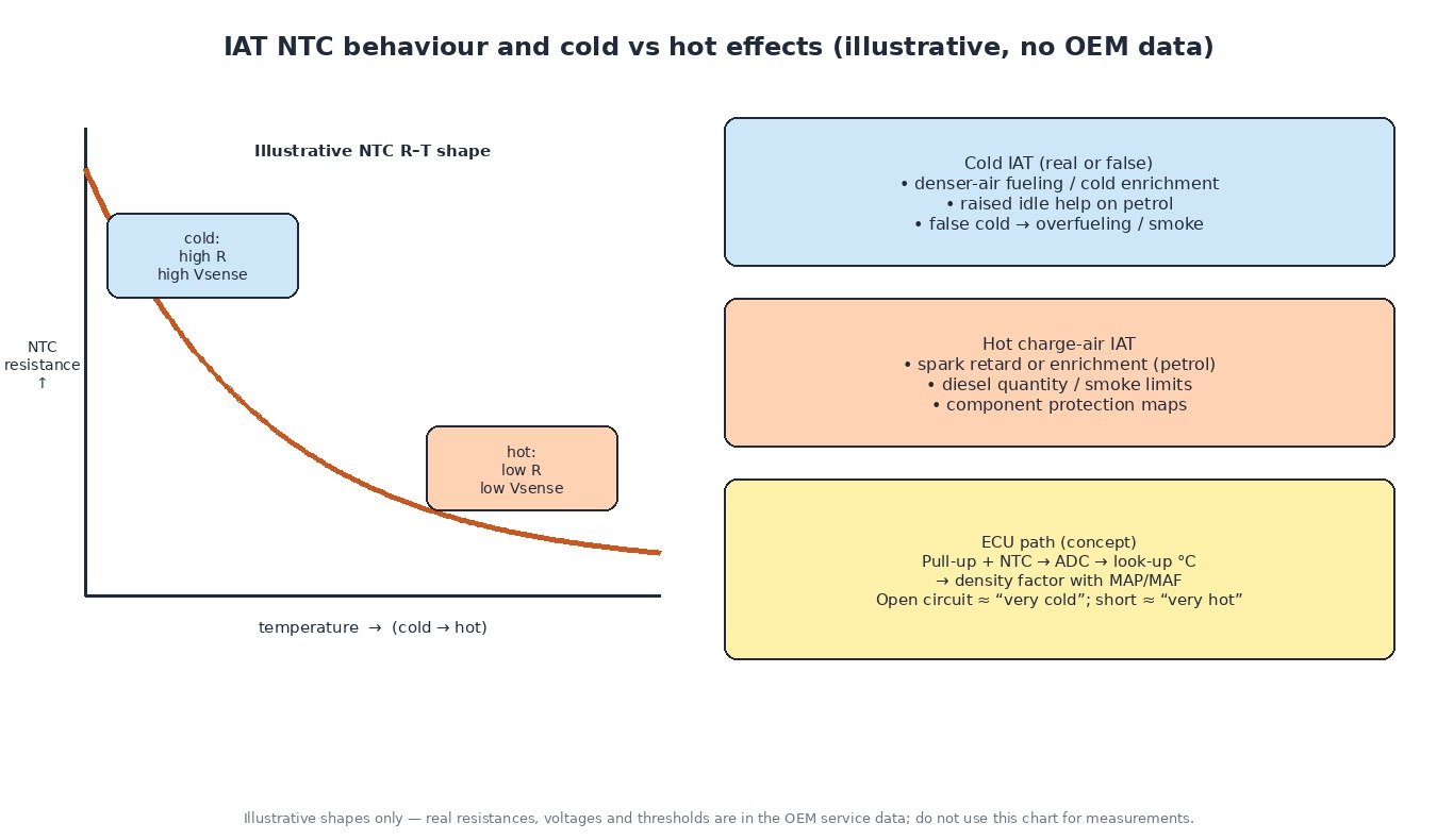
ECU strategies that depend on IAT
- Air-density correction together with MAP or MAF.
- Cold enrichment and idle stabilisation on petrol engines.
- Hot charge-air spark and fuel corrections, plus diesel smoke/quantity caps.
- Occasional links into fan or AC request maps, depending on the calibration.
When the circuit fails, many ECUs store P0110–P0114 and run on a substitute temperature. Driveability then reflects the substitute, not the weather — which is why clearing the code without fixing the circuit only hides the problem for one drive cycle.
Charge-air temperature and the intercooler
Boosted engines heat the air in the compressor. The intercooler’s job is to drop that temperature before the charge reaches the cylinders. A post-intercooler temperature that climbs quickly under load while ambient or MAF IAT stays moderate is a qualitative clue that cooler airflow or heat rejection is poor (blocked fins, failed fan shroud, recirculation). It is not a licence to invent pressure-drop numbers; use OEM tests where published. For diagnostics, log both sensors when both exist: disagreement under load is more informative than a single static reading in the bay.
Practical diagnostic sequence
- Codes and freeze frame — note low vs high vs intermittent vs range/performance, and whether MAF or boost codes are present too.
- Cold engine key-on compare — IAT should approximately match ambient; a large gap with the engine cold points to sensor or wiring.
- Watch heat-soak — after a hot shutdown, underhood IAT can rise; confirm it falls again with road airflow.
- Resistance and circuit checks — measure the NTC at a known temperature against the service chart; prove reference, ground and signal for opens and shorts.
- Inspect the MAF housing if IAT is integrated — oil film and debris skew temperature and airflow together (related P0101 territory).
- TMAP connector and shared grounds — a damaged boost/temperature plug can set P0238-style boost codes alongside odd charge-air temps.
- Symptom match — false cold → rich/smoke; false hot → flat power, retard, derate.

Vehicle-type notes
Cars and vans usually present a single duct or MAF IAT, plus TMAP on turbo variants. Trucks may expose several PIDs (ambient, intake, charge-air); use the one that matches the complaint and the code definition. Agricultural machines suffer connector corrosion and dust in MAF housings; verify grounds before replacing sensors. Bikes often run speed-density without a MAF, so IAT errors hit mixture harder and show up sooner in fuel trims or plug colour.
Tuning notes
Do not rescale IAT in a tune to mask a faulty sensor. Hot IAT protection exists to save hardware on boosted engines; stripping it for a dyno number is unsafe. If a vehicle arrives with smoke or rich running after a remap, confirm IAT live data against ambient before changing fuel maps. Repair the circuit, then evaluate the file.
Related fault codes (DTCs)
Generic OBD-II codes (SAE J2012). OEM text and extra manufacturer codes may appear alongside these.
| Code | Meaning | Typical causes |
|---|---|---|
| P0110 | Intake Air Temperature Sensor 1 Circuit | General IAT circuit fault: open, short, failed sensor or connector |
| P0111 | Intake Air Temperature Sensor 1 Circuit Range/Performance | Implausible reading vs ambient/ECT, intermittent signal, contaminated MAF-integrated sensor |
| P0112 | Intake Air Temperature Sensor 1 Circuit Low | Signal shorted to ground or failed sensor (often reads very hot) |
| P0113 | Intake Air Temperature Sensor 1 Circuit High | Open circuit, poor connector or failed sensor (often reads very cold) |
| P0114 | Intake Air Temperature Sensor 1 Circuit Intermittent | Loose pin, chafed harness, heat-related intermittent open/short |
| P0070 | Ambient Air Temperature Sensor Circuit | Fault in the ambient (outside air) temperature circuit where fitted |
| P0071 | Ambient Air Temperature Sensor Range/Performance | Implausible ambient reading vs IAT/ECT after soak |
| P0072 | Ambient Air Temperature Sensor Circuit Low | Ambient sensor or wiring shorted low |
| P0073 | Ambient Air Temperature Sensor Circuit High | Ambient sensor open or shorted high |
| P0127 | Intake Air Temperature Too High | Genuine hot charge air, heat-soaked sensor, failed intercooler airflow, or skewed high reading |
| P0101 | Mass or Volume Air Flow Sensor Circuit Range/Performance | MAF plausibility fault; can accompany a contaminated MAF housing that also holds the IAT element |
| P0238 | Turbocharger/Supercharger Boost Sensor “A” Circuit High | Boost/TMAP pressure circuit high; check shared TMAP connectors when diagnosing charge-air temperature issues |
Closing
Treat IAT codes as density and protection problems, not as a simple part-swap. Prove the reading, prove the wiring, then decide whether the sensor, the cooler or the harness is at fault.
Looking for an original file or an engineered calibration? Browse the ECUFlashFiles shop.