
The “Check Hybrid System” warning appears, the car will not go into READY, and the scan tool shows P0A80 or P0AA6. Hybrid faults can look intimidating, but most follow a logical pattern once you know how the system is built and which control unit is responsible for what. This guide walks through the parts of a hybrid drive, the most common failure areas, the safe order of checks and the generic fault codes you are likely to see.
Know which hybrid you are working on
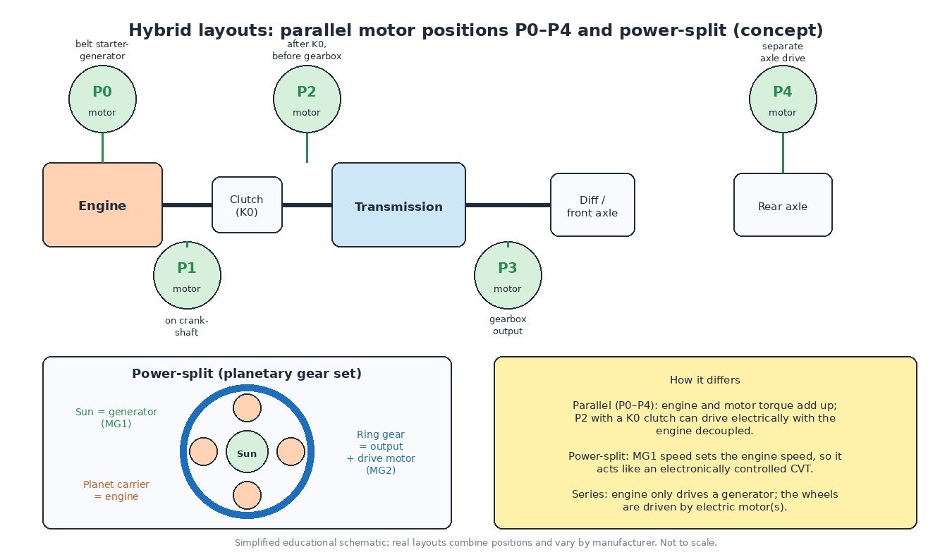
The layout decides how faults show up. A 48 V mild hybrid usually has a belt starter-generator (P0 position) that helps with stop-start and small torque assist; the engine always drives the car. A P2 hybrid places the electric motor between the engine and the gearbox with a separating clutch, so it can drive electrically with the engine disconnected. Some vehicles add a P4 motor on the rear axle. A power-split system uses a planetary gear set: the engine drives the planet carrier, a generator sits on the sun gear and the drive motor is connected to the ring gear and output. In a series hybrid, the engine only runs a generator.
Knowing the layout tells you what the engine ECU can still do on its own. On a power-split design, for example, an engine fault quickly becomes a hybrid fault, because the generator is used to crank and control the engine.
Main components and what fails
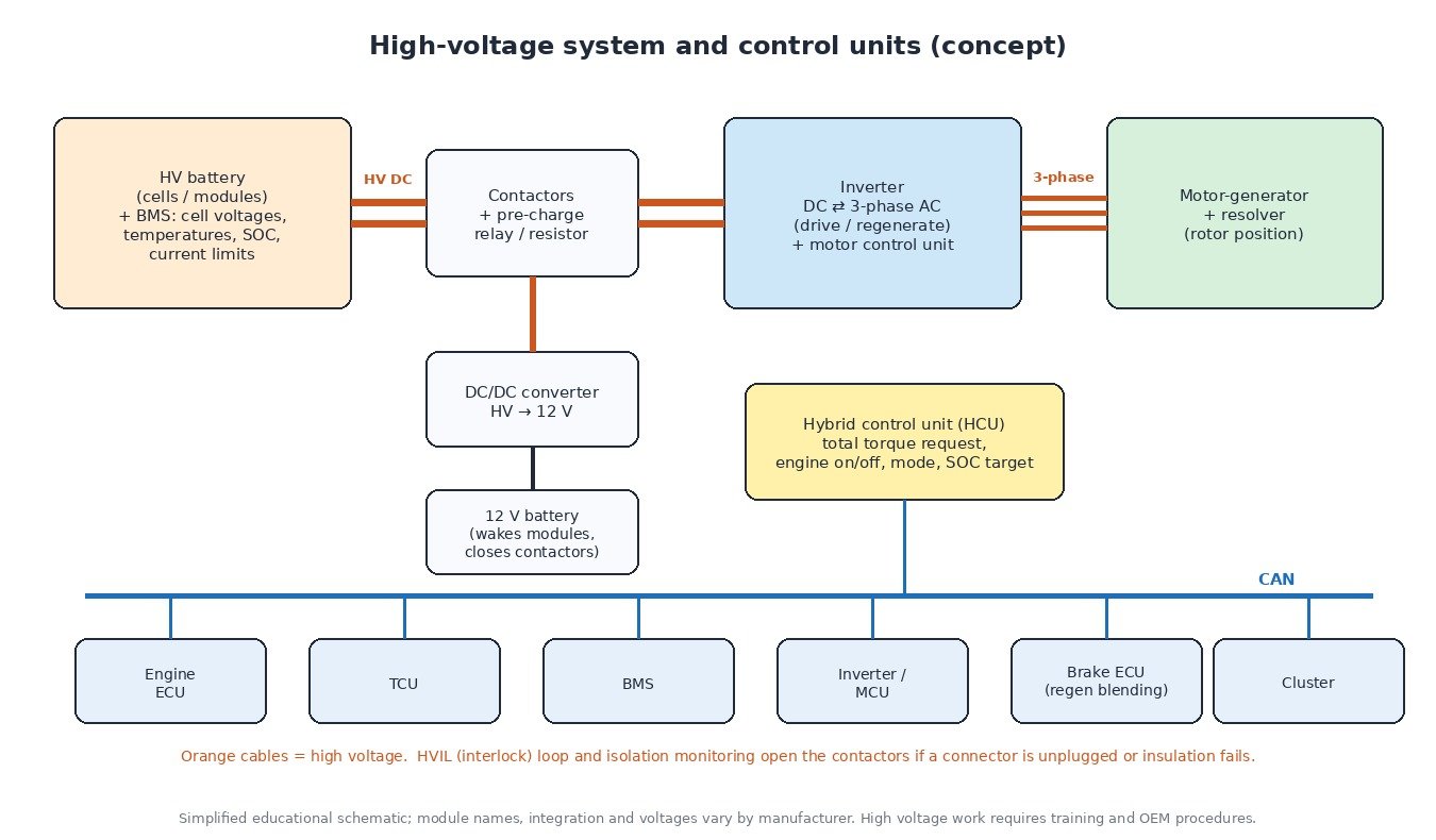
- HV battery and BMS: cells grouped into modules or blocks. The battery management system measures voltages, temperatures and current, and limits charge and discharge power. Ageing modules develop higher internal resistance and drift apart in voltage.
- Battery cooling: an air fan with an intake in the cabin or a liquid circuit. Blocked intakes and dirty fans are a frequent cause of over-temperature and power limitation.
- Inverter and converter: switch DC to three-phase AC for the motor and back again during regeneration; many systems also boost voltage. They depend on their own coolant circuit and electric pump.
- Motor-generators and resolvers: the resolver tells the inverter the exact rotor position; a fault here means the motor cannot be controlled.
- DC/DC converter and 12 V battery: the converter charges the 12 V battery from the HV system. The 12 V battery wakes all modules and closes the contactors.
- Safety circuits: the high-voltage interlock loop (HVIL) runs through HV connectors and the service plug, and an isolation monitor checks insulation between the HV system and the body.
Safe diagnostic order
- Test the 12 V battery and its connections. A weak 12 V supply prevents READY, sets communication faults and confuses the hybrid modules. It is the cheapest fix and often the right one.
- Read every control unit. Engine ECU, hybrid control unit, BMS, inverter and brake ECU each keep their own fault memory. Note freeze-frame data and which fault set first.
- Check cooling before condemning parts. Inspect the battery air intake and fan, inverter coolant level and the electric pump. Many inverter and converter codes start with poor cooling.
- Use live data. Compare module or block voltages under load and at rest, look at the spread between highest and lowest, and check battery temperature sensors against each other.
- Insulation and interlock faults need extra care. P0AA6 means the HV system may be leaking to the chassis. Do not guess: follow the manufacturer’s isolation test procedure.
- Only trained, equipped technicians open HV components. De-energise per the service manual, remove the service disconnect, wait the specified time, wear rated insulated gloves and verify zero voltage.
Cars, vans, trucks, tractors and bikes

Most hybrid diagnostics today happen on cars and SUVs. Delivery vans, distribution trucks and city buses use parallel or series hybrids with larger packs and liquid cooling; their codes may come over J1939 as SPN and FMI rather than P-codes. On agricultural machines electrification is still emerging, mostly for implements and auxiliaries. Hybrid motorbikes are rare and use manufacturer-specific tools.
Engine software on a hybrid
The engine ECU on a hybrid works under the hybrid control unit, which coordinates engine torque with motor torque, battery limits and the gearbox. That is why the engine software is matched to the rest of the system. Before replacing or reprogramming an engine ECU on a hybrid, save a full original read, keep the 12 V supply stable with a battery support unit, and make sure the software version matches the vehicle so that the hybrid modules accept it.
Related fault codes (DTCs)
Generic OBD-II hybrid codes (SAE J2012). Wording varies by manufacturer, and many brands add their own block-voltage and component codes alongside these.
| Code | Meaning | Typical causes |
|---|---|---|
| P0A0D | High Voltage System Interlock Circuit High | HVIL loop open: service plug or HV connector not fully seated, damaged interlock wiring or pins |
| P0A0F | Engine Failed to Start | Engine fault seen by the hybrid system: fuel supply, ignition, compression or engine sensor problems, empty tank |
| P0A1D | Hybrid Powertrain Control Module | Internal fault of the hybrid control unit, supply or ground problems, software issue |
| P0A1F | Battery Energy Control Module | BMS / battery control module fault, its power or ground, internal communication fault |
| P0A78 | Drive Motor “A” Inverter Performance | Inverter fault, inverter overheating, motor or HV cable insulation problem; check cooling first |
| P0A7E | Hybrid Battery Pack Over Temperature | Blocked battery cooling air intake or filter, failed cooling fan or pump, faulty temperature sensor |
| P0A7F | Hybrid Battery Pack Deterioration | Ageing cells or modules with high internal resistance, module imbalance, poor bus-bar connections |
| P0A80 | Replace Hybrid Battery Pack | Voltage difference between blocks/modules too large; often stored with manufacturer block-voltage codes |
| P0A93 | Inverter “A” Cooling System Performance | Low coolant in the inverter circuit, failed electric coolant pump, air in the circuit, blocked radiator or hoses |
| P0A94 | DC/DC Converter Performance | Boost or DC/DC converter fault, overheating from poor inverter cooling, internal failure of the converter assembly |
| P0AA6 | Hybrid Battery Voltage System Isolation Fault | Insulation breakdown between HV system and chassis: damaged orange cable, coolant or moisture in HV parts, electric A/C compressor, battery leakage |
Closing
12 V battery, every module, cooling, live data, then HV tests by the book: that order solves most hybrid faults safely.
Looking for an original stock ECU file for your vehicle? Browse the ECUFlashFiles catalogue.