
A diesel that cranks for a long time on a cold morning, smokes white and runs rough for the first minute usually has a cold-start problem, and the glow plug system is the first place to look. But hard starting has many causes, and a new set of plugs does not always fix it. This guide walks through how diesel preheating works, what the glow control unit does, which fault codes it sets and how to find the real fault on cars, vans, trucks and farm machinery.

How preheating helps a cold diesel
A diesel ignites its fuel with hot compressed air. In a cold engine the cylinder walls and piston absorb that heat, so the air may not get hot enough for clean ignition. A glow plug is a small electric heater whose tip sits in the combustion chamber, giving the injected fuel a hot spot to ignite on. The ECU controls it using coolant temperature, engine speed, load and battery voltage.
Plug technology in brief
Older engines use self-regulating steel plugs that run on battery voltage and limit their own current as they heat up. Most current diesels use low-voltage fast-heating plugs, steel or ceramic, driven by an electronic glow control unit. Ceramic elements survive higher temperatures and long post-glow, but crack if dropped or overtightened. A few engines use plugs with a built-in combustion pressure sensor.
What the glow control unit does
The glow control unit (GCU) sits between the ECU and the plugs. The ECU asks for a glow level, and the GCU switches each plug with PWM to create that effective voltage, correcting for battery voltage. It measures the current in every channel and reports faults per cylinder. On simple relay systems all plugs switch together and a single failed plug may go unnoticed until starts get worse.
The three glow phases
- Pre-glow before cranking, with the dash lamp on; its length depends on coolant temperature.
- Start glow during cranking.
- Post-glow after the engine starts, tapering off as the engine warms and cut at higher rpm or load. It reduces smoke, knock and emissions, and some engines also glow during DPF regeneration.

Heavy-duty and off-road systems
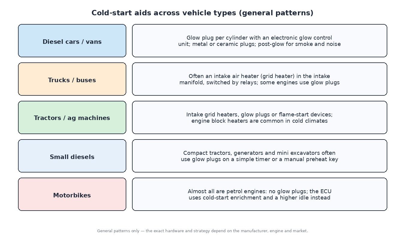
Trucks, buses and many tractors often use an intake air heater: a grid element in the intake manifold, switched by heavy relays, that warms the air before it enters the cylinders. Its main cable and relay terminals carry a high current, so corrosion and loose terminals are classic faults. Some agricultural engines use flame-start devices, and block heaters are common where winters are hard. Small diesels in generators and compact machines often have plain glow plugs on a timer or a preheat key position. Petrol motorbikes have no glow system; they rely on cold-start enrichment.
Step-by-step diagnosis
- Scan for codes and freeze-frame data, including GCU codes stored in the ECU.
- Check the coolant temperature reading on a cold engine. It should be close to the outside temperature; a sensor reading warm gives too little preheat.
- Watch the preheat lamp and command in live data, then confirm voltage at the plugs or heater during pre-glow.
- Test each plug’s current draw with a clamp meter, or measure resistance, and compare cylinders and specifications. Do not connect low-voltage plugs straight to 12 V on the bench.
- Inspect supply, fuse, relays, grounds and connectors, especially on intake heaters.
- Rule out the rest: battery and cranking speed, rail pressure during cranking, injector back-leak, air in the fuel, fuel gelling in winter and compression.
When removing plugs, work on a warm engine, use penetrating oil and the correct tool, and respect the torque specification. A snapped plug in the head means an extraction job.
Related fault codes (DTCs)
Generic OBD-II codes (SAE J2012). Manufacturer wording varies, and many brands add their own glow plug and GCU codes.
| Code | Meaning | Typical causes |
|---|---|---|
| P0380 | Glow Plug/Heater Circuit “A” | Failed glow plug or glow relay/GCU, blown fuse, open or corroded supply wiring |
| P0381 | Glow Plug/Heater Indicator Circuit | Fault in the preheat lamp circuit or instrument cluster driver |
| P0382 | Glow Plug/Heater Circuit “B” | Second glow circuit or relay bank open or shorted, failed plug on that bank |
| P0383 | Glow Plug Control Module Control Circuit Low | Command line between ECU and GCU shorted to ground, faulty GCU |
| P0384 | Glow Plug Control Module Control Circuit High | Command line shorted to voltage or open, faulty GCU or connector |
| P0670 | Glow Plug Control Module Control Circuit | Open or poor connection in the ECU-to-GCU control circuit, GCU without power or ground |
| P0671 | Cylinder 1 Glow Plug Circuit | Burnt-out plug, broken terminal nut or bus bar, damaged harness to cylinder 1 |
| P0672 | Cylinder 2 Glow Plug Circuit | As P0671, for cylinder 2 |
| P0673 | Cylinder 3 Glow Plug Circuit | As P0671, for cylinder 3 |
| P0674 | Cylinder 4 Glow Plug Circuit | As P0671, for cylinder 4 |
| P0675 | Cylinder 5 Glow Plug Circuit | As P0671, for cylinder 5 |
| P0676 | Cylinder 6 Glow Plug Circuit | As P0671, for cylinder 6 |
| P0677–P0682 | Cylinder 7–12 Glow Plug Circuit | As P0671, for cylinders 7 to 12 on larger engines |
| P0683 | Glow Plug Control Module to PCM Communication Circuit | Open or shorted diagnostic/communication line, GCU fault |
| P0684 | Glow Plug Control Module to PCM Communication Circuit Range/Performance | Intermittent connection, corrupted signal, incompatible or faulty GCU |
| P0540 | Intake Air Heater “A” Circuit | Grid heater, heater relay or high-current cable fault (common on trucks and tractors) |
| P0541 | Intake Air Heater “A” Circuit Low | Relay control or heater circuit shorted to ground |
| P0542 | Intake Air Heater “A” Circuit High | Relay stuck closed or circuit shorted to voltage |
| P0543 | Intake Air Heater “A” Circuit Open | Burnt heater element, loose or corroded main terminal, open relay |
| P0117 | Engine Coolant Temperature Sensor 1 Circuit Low | Sensor or wiring shorted to ground; the ECU sees a very hot engine and may shorten preheat |
| P0118 | Engine Coolant Temperature Sensor 1 Circuit High | Open circuit or failed sensor; the ECU sees a very cold engine and uses substitute values |
| P0562 | System Voltage Low | Weak battery, charging fault, poor grounds; glow and cranking performance suffer |
| P0335 | Crankshaft Position Sensor “A” Circuit | No rpm signal: cranks but no start, independent of the glow system |
| P0087 | Fuel Rail/System Pressure – Too Low | Low-pressure supply, filter, pump or injector leakage; a common cause of hard starting that is mistaken for glow faults |
Tuning notes
Preheat timing, start quantity and warm-up injection are calibrated by the manufacturer and are best left that way in a tuning file: more start fuel only adds smoke. Repair any glow, ECT or fuel-supply fault before evaluating a remap, otherwise cold-start complaints get blamed on the file.
Looking for an original file or an engineered calibration? Browse the ECUFlashFiles shop.