
If you log a diesel during a regeneration or a petrol turbo on a long full-throttle pull, one channel tells you more about engine stress than almost any other: exhaust gas temperature. EGT sensors let the ECU protect the turbocharger and aftertreatment, and they decide when a DPF regeneration or AdBlue dosing is allowed. This technician-focused guide covers sensor construction, typical mounting positions, ECU strategies and a practical diagnostic routine for the P0544-family and P2428 codes.
What an EGT sensor actually measures
The sensor reports the temperature of the gas flowing past its tip at one point in the exhaust. That temperature changes with load, fuelling, boost, ignition or injection timing and the state of the catalysts downstream. The ECU combines the measured values with an internal exhaust temperature model, so even engines with few sensors can estimate temperatures at points that have none.
Sensor construction: resistive or thermocouple
Resistive elements
The most common OE design places a resistive element inside a sealed stainless tip. Platinum thin-film elements raise their resistance as temperature rises (PTC), while NTC types lower it. The ECU supplies a reference through an internal pull-up resistor and reads the voltage across the sensor. Because the circuit is a simple divider, an open circuit or a short to ground drives the reading to one end of the scale, which is what triggers the circuit high and circuit low codes.
Thermocouples
A thermocouple joins two different alloys at the tip. Heating that junction produces a millivolt-level voltage that rises with temperature. It needs an amplifier and cold-junction compensation before an ECU or gauge can use it. Type K thermocouples are the usual choice for aftermarket pyrometers and test-bench logging, and some manufacturers use thermocouples with a dedicated amplifier box.
Whatever the type, the tip mass matters. Heavily sheathed sensors survive vibration and heat but lag behind sudden changes, so compare trends rather than single samples when you log.

Typical mounting positions
Numbering follows the gas flow, and the exact layout depends on engine and emissions level:
- Before the turbine to guard the turbocharger and manifold, common on petrol turbo engines and many diesels.
- Before the DOC to check oxidation catalyst light-off before a regeneration starts.
- Before the DPF so the ECU can hold regeneration temperature without overshooting.
- Before the SCR catalyst because AdBlue/DEF dosing needs a minimum temperature to avoid deposits.
ECU strategies that use EGT
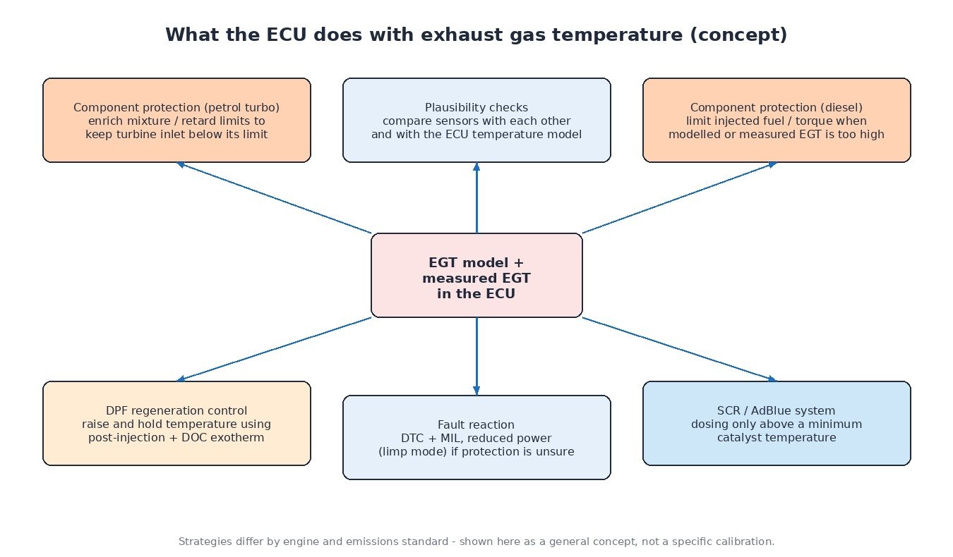
On a petrol turbo engine, the classic protection is enrichment: running richer than stoichiometric cools the exhaust when the turbine inlet temperature approaches its limit, with boost or ignition limits as extra measures. A diesel runs lean all the time, so protection works the other way: the ECU trims injected fuel and therefore torque. During DPF regeneration, post-injected fuel burns in the DOC, and the ECU uses the DOC and DPF inlet readings as feedback to reach and hold the target. SCR logic waits for its inlet sensor to reach the dosing threshold. Finally, the ECU runs plausibility checks between sensors and against its model, and reacts to failures with a DTC, a warning lamp and often a power reduction.
A practical diagnostic routine
- Identify the exact sensor. Bank and sensor numbers in the code map to physical positions in service data; on multi-sensor diesels it is easy to replace the wrong one.
- Cold-soak test. With the engine cold overnight, all EGT channels should read close to ambient and close to each other at key-on.
- Circuit test. Disconnect the sensor, check its resistance against specification, then check reference, signal and ground in the harness. Inspect for melted insulation, broken conductors near the exhaust and corroded connector pins.
- Road test with logging. Watch how each sensor responds to load steps. A flat line or a reading that lags far behind the others suggests a failing sensor.
- Over-temperature codes. Before blaming the sensor, check for a blocked DPF or exhaust, injector problems, boost leaks or a faulty sensor upstream feeding the model. Confirm with a pyrometer if possible.
Cars, trucks, tractors and motorcycles
Diesel cars and vans meeting Euro 5/6 typically use two to four sensors. Heavy trucks and Stage IV/V agricultural machines follow the same principle with long harnesses that face vibration and heat; repeated EGT-related derates under heavy PTO or field work are often a symptom of aftertreatment or fuelling problems rather than the sensor itself. Motorcycles seldom carry factory EGT sensors and usually rely on modelling, with pyrometers added for racing or turbo projects.
Related fault codes (DTCs)
Generic SAE J2012 definitions. Physical locations vary by manufacturer.
| Code | Meaning | Typical causes |
|---|---|---|
| P0544 | Exhaust Gas Temperature Sensor Circuit Bank 1 Sensor 1 | Sensor, wiring or connector |
| P0545 | Exhaust Gas Temperature Sensor Circuit Low Bank 1 Sensor 1 | Signal shorted to ground, sensor fault |
| P0546 | Exhaust Gas Temperature Sensor Circuit High Bank 1 Sensor 1 | Open circuit, disconnected or burnt harness |
| P0547 | Exhaust Gas Temperature Sensor Circuit Bank 2 Sensor 1 | Bank 2 sensor or wiring |
| P0548 | Exhaust Gas Temperature Sensor Circuit Low Bank 2 Sensor 1 | Short to ground, sensor fault |
| P0549 | Exhaust Gas Temperature Sensor Circuit High Bank 2 Sensor 1 | Open circuit, connector |
| P2031 | Exhaust Gas Temperature Sensor Circuit Bank 1 Sensor 2 | Downstream sensor or wiring |
| P2032 | Exhaust Gas Temperature Sensor Circuit Low Bank 1 Sensor 2 | Short to ground, sensor fault |
| P2033 | Exhaust Gas Temperature Sensor Circuit High Bank 1 Sensor 2 | Open circuit, heat-damaged harness |
| P2080 | Exhaust Gas Temperature Sensor Circuit Range/Performance Bank 1 Sensor 1 | Drifting or slow sensor, implausible vs model |
| P2081 | Exhaust Gas Temperature Sensor Circuit Intermittent Bank 1 Sensor 1 | Intermittent connection |
| P2084 | Exhaust Gas Temperature Sensor Circuit Range/Performance Bank 1 Sensor 2 | Drifting sensor, nearby exhaust leak |
| P2428 | Exhaust Gas Temperature Too High Bank 1 | Exhaust/DPF restriction, fuelling or boost fault, sensor error |
| P2429 | Exhaust Gas Temperature Too High Bank 2 | Same as P2428 for bank 2 |
Tuning note
EGT is a hard boundary for any performance calibration. Extra fuel and boost raise exhaust temperature, so a sound file keeps the temperature model, sensor monitoring and protection derates working and aims for sensible logged values under sustained load. Fix sensor, exhaust and aftertreatment faults before tuning instead of calibrating around them.
Need a calibration that keeps EGT protection intact? Browse tuning files at ECUFlashFiles.