
If the coolant temperature signal is wrong, the engine control unit (ECU) makes the wrong decisions about fuelling, idle, fans and warm-up enables. That is why P0117, P0118 and related codes deserve a structured approach instead of a blind sensor swap. This guide explains the ECT sensor circuit, how it ties into the thermostat–radiator–pump loop, how the ECU uses the reading, and a practical order of checks for cars, vans, trucks, agricultural machines and motorcycles.
Cooling hardware the ECU depends on
Heat leaves the cylinders into coolant in the block and head jackets. A water pump keeps that coolant moving. While the thermostat is closed, flow stays in a short loop so the engine reaches operating temperature promptly. When the thermostat opens, coolant flows through the radiator, where airflow – helped by an electric fan when needed – carries the heat away. A pressurised expansion tank keeps the boiling point high enough for normal loads. The ECT sensor is usually threaded into the thermostat housing or an adjacent coolant passage so it sees a temperature the ECU can trust.
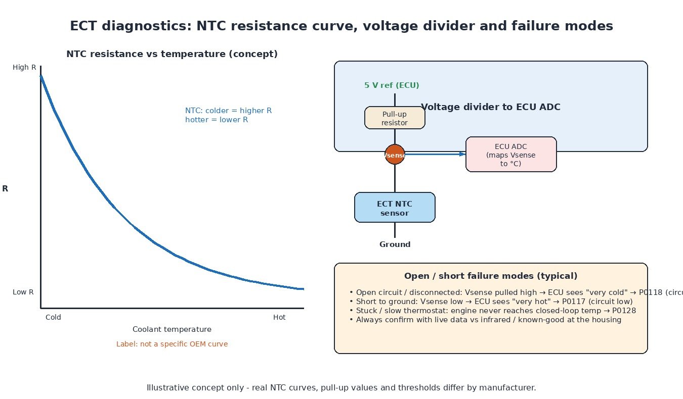
ECT circuit: NTC, divider and ADC
Most ECT sensors are NTC thermistors: resistance falls as temperature rises. The ECU supplies a reference through a pull-up resistor; the junction voltage is digitised and mapped to temperature. With the engine cold you expect a high resistance and a high sense voltage; with the engine hot you expect the opposite. That electrical behaviour explains the classic failure signatures: an open wire or unplugged connector pulls the sense line high (ECU thinks “ice cold,” often P0118), while a short to ground pulls it low (ECU thinks “overheating,” often P0117). Range/performance and intermittent codes (P0116, P0119) cover signals that move, but not in a plausible way.
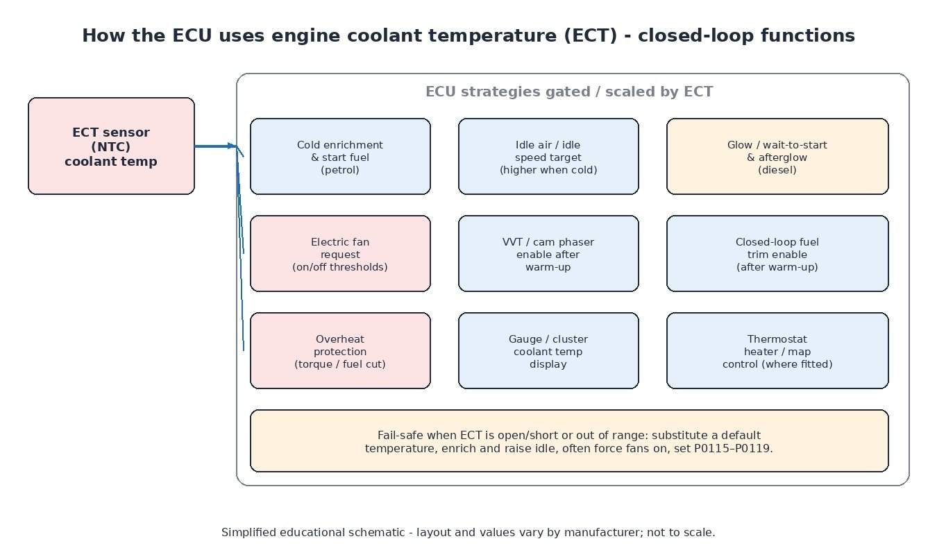
ECU strategies that read ECT
- Enrichment and cranking fuel – cold walls need more fuel for a clean start and stable run-up on petrol engines.
- Idle control – target idle speed and idle air are raised when cold, then reduced as temperature climbs.
- Fan control – the ECU requests fan speed or relay stages from coolant temperature (and often AC pressure), which is why fan circuit codes sit next to ECT codes in many fault lists.
- Diesel glow and afterglow – glow duration and wait-to-start lamps follow coolant (and sometimes ambient) temperature.
- System enables – variable valve timing, closed-loop fuel trim and some emissions devices wait for a minimum coolant temperature.
- Protection – above a hard threshold the ECU may limit torque or fuel; P0217 flags an over-temperature condition.
Thermostat codes are not the same as sensor codes
P0125 and P0128 point at the engine not reaching the temperature the calibration expects for closed-loop fuel control or thermostat regulation. A stuck-open thermostat, low coolant or a chronically biased ECT reading are common causes. P0217 is the opposite problem: the engine really is too hot, or the ECU believes it is – so verify with a second temperature measurement before condemning the head gasket or the radiator.
Diagnostic order that saves time
- Codes + freeze frame + live data. Note whether the fault is electrical (low/high/intermittent) or thermal (P0125/P0128/P0217).
- Sanity-check ECT at key-on cold. It should be close to ambient. If the cluster gauge and the scan-tool ECT disagree, decide which path is lying.
- Warm-up curve. Watch ECT rise after a cold start. Flatline near ambient suggests open circuit or unplugged sensor; an instant jump to maximum suggests a short; a very slow rise with a hot upper hose pattern suggests thermostat or low-flow issues.
- Electrical tests. Resistance vs temperature chart, reference and ground integrity, harness chafe near the thermostat housing, coolant intrusion in the connector.
- Fan path. For P0480–P0483, command the fan, check relay supply/ground, motor current draw and any PWM fan module feedback.
- Mechanical cooling checks. Level, bleed procedure, pump drive, radiator restriction, and electric pump command where the vehicle uses one.
Across vehicle types
Cars and vans share the NTC-plus-electric-fan pattern. Trucks and tractors often combine large mechanical or viscous fans with jacket thermostats and separate charge-air cooling; the ECT input still drives glow, protection and derate logic. Liquid-cooled bikes pack the same sensor and fan ideas into a smaller radiator and head casting. In every case, treat “temperature code” as a system diagnosis, not an automatic sensor sale.
Related fault codes (DTCs)
Verified generic SAE J2012 descriptions. Always cross-check letter suffixes and manufacturer codes in the service information for the vehicle on the bench.
| Code | Meaning | Typical causes |
|---|---|---|
| P0115 | Engine Coolant Temperature Sensor 1 Circuit | Wiring, connector corrosion, failed ECT sensor |
| P0116 | Engine Coolant Temperature Sensor 1 Circuit Range/Performance | Implausible vs IAT/oil temp, partial short, sticking thermostat |
| P0117 | Engine Coolant Temperature Sensor 1 Circuit Low | Signal short to ground, internal sensor short (hot reading) |
| P0118 | Engine Coolant Temperature Sensor 1 Circuit High | Open signal or ground, unplugged sensor (cold reading) |
| P0119 | Engine Coolant Temperature Sensor 1 Circuit Intermittent | Loose terminal, broken wire flexing with engine movement |
| P0125 | Insufficient Coolant Temperature for Closed Loop Fuel Control | Thermostat open, low coolant, ECT reading too low |
| P0128 | Coolant Thermostat (Coolant Temperature Below Thermostat Regulating Temperature) | Thermostat stuck open / early opening, cooling system fault |
| P0217 | Engine Coolant Over-Temperature Condition | Cooling failure, failed fan, pump, blockage; confirm real overheat |
| P0480 | Fan 1 Control Circuit | Relay coil/contacts, fan motor, ECU output, fuse |
| P0481 | Fan 2 Control Circuit | Second fan stage wiring or relay |
| P0482 | Fan 3 Control Circuit | Third fan stage (multi-fan packs) |
| P0483 | Fan Rationality Check | Commanded fan behaviour does not match monitored result |
Tuning note
Temperature-based enrichment, fan maps and derate tables can be refined in a custom file, but overheat monitors and substitute-temperature fail-safes are protective logic. Do not calibrate around a failed thermostat or a damaged ECT circuit. Repair the cooling and sensing path, verify live ECT against a real temperature reference, then apply performance changes with protection left intact.
Looking for OEM-style calibrations with temperature protection left on? Browse tuning files at ECUFlashFiles.