
If sequential injection and coil-on-plug ignition had a single foundation, it would be engine position sensing. The crankshaft position (CKP) sensor and camshaft position (CMP) sensor tell the ECU how fast the crank is turning, where it is in rotation, and which cylinder is on which stroke. This article walks through VR versus Hall sensors, reluctor wheels, sync logic, diagnostics and tuning implications — for cars, vans, trucks, farm machinery and motorcycles.
Speed, position and phase
CKP reads a toothed ring on the crankshaft, flywheel or damper. Decoded correctly, it delivers rpm and crank angle within one revolution. CMP reads a target on a camshaft (or, on some diesel pumps, on the pump shaft). It answers the phase question the crank alone cannot: in a four-stroke, the same crank angle occurs twice per full cycle — once on compression and once on exhaust. Cam information, or a second sync track, picks the right one.
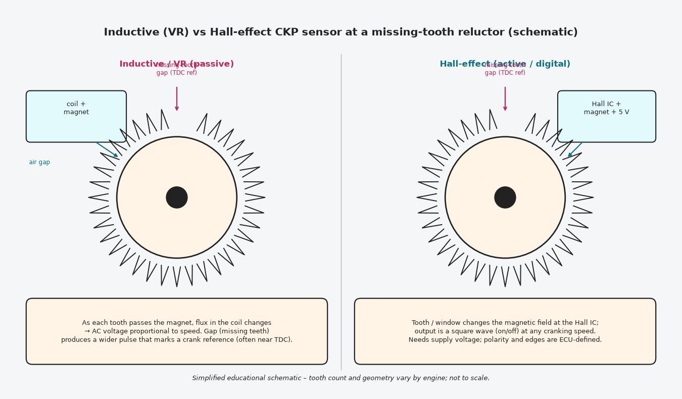
How inductive and Hall sensors differ
Inductive (VR) sensors are passive: a magnet and coil. Moving teeth change flux and generate an alternating voltage. Output grows with rpm, so cranking signals are small and high-speed signals are large. The ECU processes zero-crossings and recognises the longer interval at a missing-tooth gap as its absolute reference.
Hall-effect sensors are active. They need a supply (often 5 V). A Hall element switches as teeth or slots pass, producing a digital square wave with usable edges even while cranking slowly. Amplitude does not depend on speed the way a VR signal does; edge direction and duty are part of the OEM design.
On both designs the air gap between sensor tip and teeth must match the service data. Debris on the magnet, a bent bracket or a loose sensor shifts the gap and can create intermittent dropouts long before a hard open circuit appears.
Reluctor wheels and the missing-tooth reference
Common crank patterns omit one or two teeth from an otherwise regular wheel (60-2, 36-1, 36-2 and similar). That gap is the landmark the tooth decoder uses to lock onto a known crank angle, frequently near cylinder 1 TDC. Other layouts use evenly spaced teeth plus a separate CMP pulse, or a dual-track crank sensor with a dedicated sync mark. If the mechanical wheel is cracked, has filled or broken teeth, or was replaced with the wrong part, the ECU sees an implausible pattern and sets range/performance codes such as P0336.
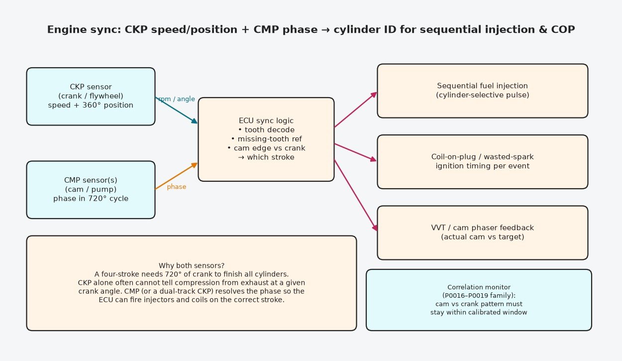
Building sync for injection, ignition and VVT
Once the missing-tooth (or sync) mark is locked and cam phase is known, the ECU can assign each crank event to a cylinder and stroke. That enables:
- cylinder-selective sequential injection;
- correct coil-on-plug or wasted-spark timing;
- closed-loop control of cam phasers, comparing commanded VVT angle with the CMP reading.
Monitors continuously check that cam edges stay inside a calibrated window relative to the crank pattern. Drift from a jumped belt, stretched chain, slipped damper, stuck phaser or damaged tone wheel triggers crank/cam correlation codes (P0016–P0019 family).
Typical failure modes
- Incorrect air gap after sensor, clutch or flywheel replacement.
- Cracked, bent or partially missing reluctor teeth — especially on dual-mass flywheels and exposed rings.
- Swarf or clutch dust stuck to the sensor magnet.
- Oil soaking CMP connectors on cam covers; water ingress after pressure-washing.
- Chafed wiring on sharp edges or against hot turbo/exhaust parts.
- Mechanical timing errors with electrically healthy sensors (belt/chain, phaser).
- Internal sensor failure: open VR coil, failed Hall IC, temperature-related intermittents.
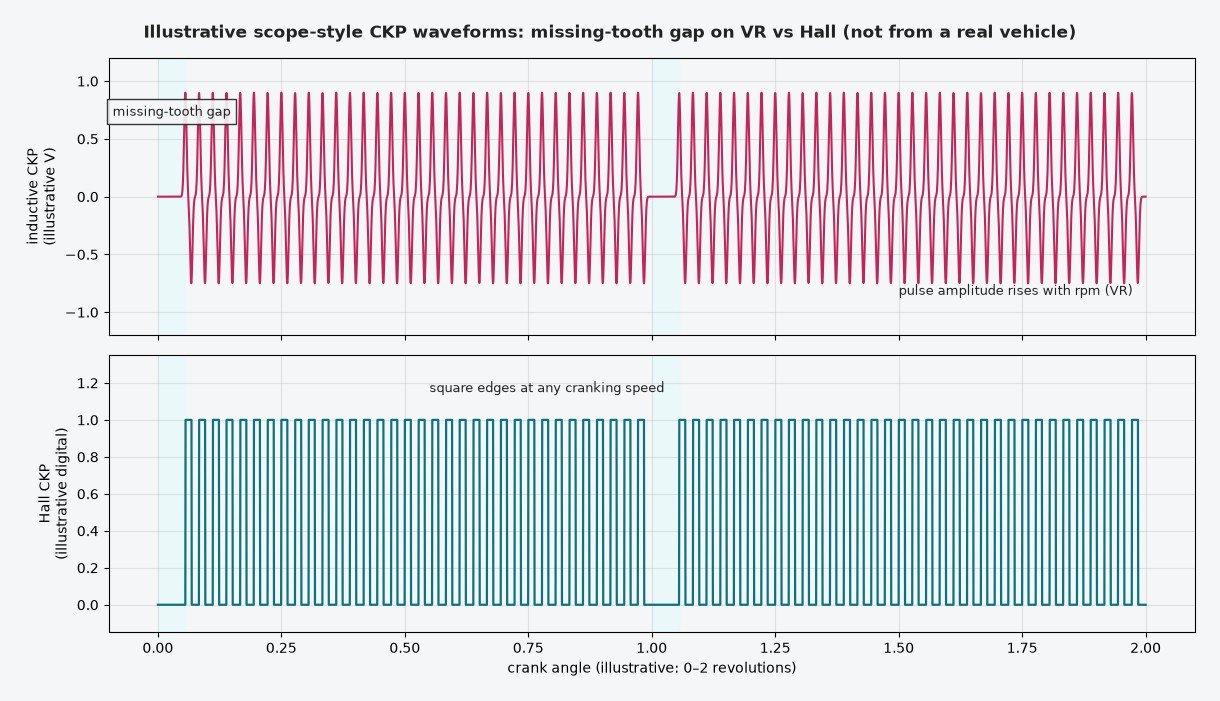
A workshop routine that finds the real fault
- Classify the code: CKP circuit, CMP circuit, intermittent, or correlation.
- Inspect connectors for oil, bent pins and poor latch; wiggle-test the harness while watching rpm and cam/crank PIDs.
- Measure or check air gap; clean and inspect the entire tone wheel circumference.
- Scope CKP through a full revolution: confirm gap location, tooth count and no missing pulses under vibration and heat.
- Overlay CMP with CKP; verify the cam edge against the expected crank window from service information.
- Cranking rpm that flickers or falls to zero points strongly at CKP or its circuit.
- Correlation codes with clean scopes → verify mechanical timing marks, chain stretch and phaser park/adapt values.
Replace sensors only after the waveform and mechanical timing make sense. Fitting a new CKP will not fix a jumped chain.
Related fault codes (DTCs)
Generic OBD-II (SAE J2012) codes for crankshaft and camshaft position sensor circuits and crank/cam correlation. Bank 1 contains cylinder 1; Sensor A is typically the intake (or sole) cam sensor and Sensor B the exhaust (or second) cam sensor where dual cams are fitted. Exact wording and enable conditions vary by manufacturer.
| Code | Meaning | Typical causes |
|---|---|---|
| P0016 | Crankshaft Position – Camshaft Position Correlation (Bank 1 Sensor A) | Timing belt/chain jumped or stretched, incorrect cam/crank timing after repair, damaged CKP or CMP tone wheel, wrong sensor air gap, wiring swapped or shorted, failed CKP/CMP sensor |
| P0017 | Crankshaft Position – Camshaft Position Correlation (Bank 1 Sensor B) | As P0016 on bank 1 cam sensor B (exhaust or second cam): jumped timing, damaged reluctor, sensor or wiring fault |
| P0018 | Crankshaft Position – Camshaft Position Correlation (Bank 2 Sensor A) | As P0016 on bank 2: jumped timing belt/chain, cam phaser stuck, damaged tone ring, sensor or wiring fault |
| P0019 | Crankshaft Position – Camshaft Position Correlation (Bank 2 Sensor B) | As P0017 on bank 2: cam/crank phase outside limits |
| P0335 | Crankshaft Position Sensor "A" Circuit | Open/short in CKP signal circuit, unplugged connector, failed sensor, damaged wiring near the engine |
| P0336 | Crankshaft Position Sensor "A" Circuit Range/Performance | Implausible tooth count or pattern: damaged or cracked reluctor/flywheel ring, wrong air gap, metallic debris, intermittent signal dropout |
| P0337 | Crankshaft Position Sensor "A" Circuit Low | Signal open or shorted to ground, failed sensor, poor ground |
| P0338 | Crankshaft Position Sensor "A" Circuit High | Signal shorted to voltage, open ground, failed sensor |
| P0339 | Crankshaft Position Sensor "A" Circuit Intermittent | Loose connector pins, chafed harness, oil or coolant in the connector, failing sensor, cracked tone wheel causing dropouts |
| P0340 | Camshaft Position Sensor "A" Circuit (Bank 1 or Single Sensor) | Open/short in CMP signal circuit, unplugged connector, failed sensor, wiring damage |
| P0341 | Camshaft Position Sensor "A" Circuit Range/Performance (Bank 1 or Single Sensor) | Implausible CMP pattern vs CKP: damaged cam tone wheel, wrong air gap, debris, intermittent signal, timing off |
| P0342 | Camshaft Position Sensor "A" Circuit Low (Bank 1 or Single Sensor) | CMP signal open or shorted to ground, failed sensor |
| P0343 | Camshaft Position Sensor "A" Circuit High (Bank 1 or Single Sensor) | CMP signal shorted to voltage, open ground, failed sensor |
| P0344 | Camshaft Position Sensor "A" Circuit Intermittent (Bank 1 or Single Sensor) | Loose pins, oil in connector, chafed harness near the cam cover, failing sensor |
| P0345 | Camshaft Position Sensor "A" Circuit (Bank 2) | Open/short in bank 2 CMP A circuit, unplugged connector, failed sensor |
| P0346 | Camshaft Position Sensor "A" Circuit Range/Performance (Bank 2) | Implausible bank 2 CMP A pattern: damaged tone wheel, air gap, debris, or timing issue |
| P0347 | Camshaft Position Sensor "A" Circuit Low (Bank 2) | Bank 2 CMP A signal open or shorted to ground, failed sensor |
| P0348 | Camshaft Position Sensor "A" Circuit High (Bank 2) | Bank 2 CMP A signal shorted to voltage, open ground, failed sensor |
| P0349 | Camshaft Position Sensor "A" Circuit Intermittent (Bank 2) | Loose connector or harness fault on bank 2 CMP A |
| P0365 | Camshaft Position Sensor "B" Circuit (Bank 1) | Open/short in CMP B (often exhaust cam) circuit on bank 1, unplugged connector, failed sensor |
| P0366 | Camshaft Position Sensor "B" Circuit Range/Performance (Bank 1) | Implausible CMP B pattern on bank 1: damaged tone wheel, wrong air gap, debris |
| P0367 | Camshaft Position Sensor "B" Circuit Low (Bank 1) | CMP B signal open or shorted to ground, failed sensor |
| P0368 | Camshaft Position Sensor "B" Circuit High (Bank 1) | CMP B signal shorted to voltage, open ground, failed sensor |
| P0369 | Camshaft Position Sensor "B" Circuit Intermittent (Bank 1) | Loose pins, oil in connector, chafed harness on bank 1 CMP B |
| P0390 | Camshaft Position Sensor "B" Circuit (Bank 2) | Open/short in bank 2 CMP B circuit, unplugged connector, failed sensor |
| P0391 | Camshaft Position Sensor "B" Circuit Range/Performance (Bank 2) | Implausible bank 2 CMP B pattern: damaged tone wheel, air gap, debris, timing issue |
| P0392 | Camshaft Position Sensor "B" Circuit Low (Bank 2) | Bank 2 CMP B signal open or shorted to ground, failed sensor |
| P0393 | Camshaft Position Sensor "B" Circuit High (Bank 2) | Bank 2 CMP B signal shorted to voltage, open ground, failed sensor |
| P0394 | Camshaft Position Sensor "B" Circuit Intermittent (Bank 2) | Loose connector or harness fault on bank 2 CMP B |
Diesel, commercial, agricultural and motorcycle notes
Light and heavy diesels still depend on CKP for rpm and injection timing reference; CMP or pump-position sensors provide phase for sequential strategies and pump control. Truck and tractor flywheel rings are large but follow the same missing-tooth and air-gap rules; harness damage from chassis flex and debris is common. Many bikes use a single CKP and wasted spark, with CMP added on more complex engines. In every case, a calibration must keep sync and correlation monitors active.
Calibration and remapping notes
Never switch off sync or correlation diagnostics to mask a P0016 or P0335-family code. Incorrect crank reference tooth or tooth offset in software moves spark and injection relative to true TDC and can cause knock, misfire or mechanical damage. After timing or sensor work, confirm correlation before evaluating a new file. Hardware integrity — gap, wheel, connectors — comes before map changes.
Key points
CKP measures crank speed and angle; CMP supplies 720° phase. VR sensors generate AC voltage; Hall sensors need power and output a square wave. Missing teeth mark the crank reference. Correlation faults are phase disagreements — electrical or mechanical. Scope first, then decide between sensor, wiring and timing gear.
Want a tune built around correct crank and cam sync? Get your tuning file from ECUFlashFiles.