
A battery warning light, a car that cranks slowly every morning, or a scan full of unrelated codes after a long idle: all of these can trace back to the charging system. Codes such as P0562 (System Voltage Low) and P2503 (Charging System Voltage Low) are common, but on modern vehicles the alternator takes orders from the ECU, a battery sensor watches every amp, and the “right” voltage changes as you drive. This guide covers how to diagnose charging and supply-voltage faults on cars, trucks, agricultural machines and motorcycles without replacing good parts.
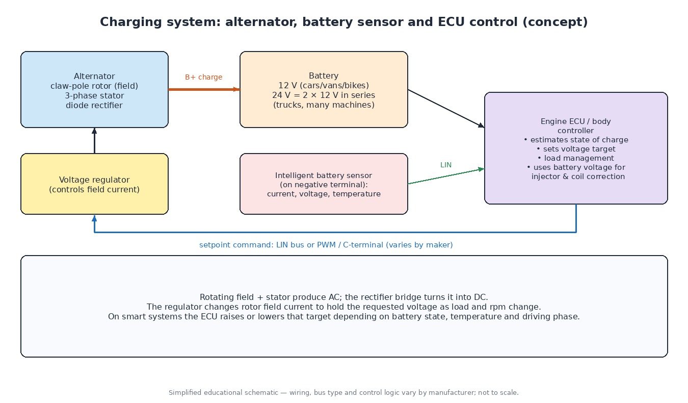
The parts that make up the system
- Alternator: a belt-driven rotor with a field winding spins inside a three-phase stator. The AC it produces is converted to DC by a diode rectifier bridge.
- Voltage regulator: varies the rotor field current to hold output at the target voltage. On smart systems the target comes from a control unit.
- Battery: 12 V on cars, vans and bikes; usually 24 V on heavy trucks and buses, commonly two 12 V batteries in series.
- Battery sensor: on many newer vehicles, a module on the negative terminal reports current, voltage and temperature so the system can estimate state of charge.
- Cables and grounds: the B+ charge lead and engine/body ground straps. They are simple parts, but often the actual fault.
Why voltage readings can mislead you
On older vehicles the regulator held a fixed target, so a quick voltmeter check told you most of the story. With ECU-controlled charging, the control unit commands a setpoint, often over LIN or a PWM wire. It lowers alternator load during hard acceleration to free up torque, raises it on overrun and braking, charges harder when the battery is cold or low, and backs off when the battery is full. A reading that changes from one moment to the next may be the strategy working as designed. Judge the system by requested versus actual values and by the manufacturer’s tests, not by one idle reading.

A step-by-step diagnostic approach
- Test the battery first with a suitable tester and charge it fully before going further. A weak battery causes most “alternator” complaints.
- Inspect the drive: belt condition and tension, tensioner and the overrunning (decoupler) pulley if fitted.
- Do voltage-drop tests under load on the B+ cable between alternator and battery and on the ground path between engine, chassis and battery negative.
- Read live data: commanded voltage, actual voltage, battery sensor current and temperature, and any regulator or LIN communication faults.
- Check for rectifier problems: a failed diode lowers output and adds AC ripple, which can disturb sensor signals and module communication.
- Check parasitic drain once modules have gone to sleep if the battery goes flat while parked.
- Register or code a replacement battery where the manufacturer requires it, so the charging strategy knows a new battery is fitted.
Knock-on faults from low voltage
The engine ECU corrects injector timing and coil dwell for supply voltage, and electronic throttle, EGR, wastegate and fuel pump drivers all need adequate voltage to follow their commands. When voltage dips, especially during cranking, you may see stored codes for sensors and actuators that are actually fine, network codes from modules that reset, or a short limp mode. Fix the supply problem, clear codes and re-test before chasing those secondary faults.

Differences by vehicle type
Cars and vans: ECU-controlled regulators, battery sensors and start-stop are common; battery registration matters on many brands. Trucks and buses: 24 V systems with high-output alternators and long cable runs, so voltage drops at grounds and junction points are frequent faults. Agricultural machines: big electrical loads, vibration, dust and wet conditions are hard on B+ studs and connectors. Motorcycles: usually a permanent-magnet stator and a regulator/rectifier; check for burnt connectors and test the stator and regulator separately before replacing either.
Before you read or write an ECU
A stable supply is essential when flashing. A voltage drop during a write can interrupt programming and leave an ECU that will not start. Connect a battery support unit or bench power supply, switch off unnecessary loads, and clear any old low-voltage codes so they are not confused with problems after a new file is installed.
Related fault codes (DTCs)
Generic OBD-II codes per SAE J2012. Exact wording varies by manufacturer, and many brands log additional body-module, battery-sensor or network codes for the same faults.
| Code | Meaning | Typical causes |
|---|---|---|
| P0560 | System Voltage | General supply voltage fault seen by the ECU: weak battery, poor ground, charging problem |
| P0561 | System Voltage Unstable | Loose battery terminals or B+ cable, intermittent ground, failing regulator, worn brushes |
| P0562 | System Voltage Low | Discharged or failing battery, alternator not charging, slipping belt, high resistance in charge or ground cables |
| P0563 | System Voltage High | Regulator stuck in full field, incorrect jump-start or charger connection, wrong setpoint command |
| P0620 | Generator Control Circuit | Open or short in the ECU-to-regulator control wire, faulty regulator, connector corrosion |
| P0621 | Generator Lamp “L” Terminal Control Circuit | Fault in the L-terminal/charge-lamp circuit, regulator fault, wiring damage |
| P0622 | Generator Field “F” Terminal Control Circuit | Field monitoring circuit fault, regulator or rotor field problem, wiring |
| P0625 | Generator Field Terminal Circuit Low | Field/monitor signal shorted to ground or open, regulator fault |
| P0626 | Generator Field Terminal Circuit High | Field/monitor signal shorted to voltage, regulator fault |
| P065B | Generator Control Circuit Range/Performance | Alternator output does not follow the ECU command: worn regulator or brushes, belt slip, overloaded system |
| P2500 | Generator Lamp/L-Terminal Circuit Low | L-terminal circuit shorted low or open, regulator fault |
| P2501 | Generator Lamp/L-Terminal Circuit High | L-terminal circuit shorted high, regulator fault |
| P2502 | Charging System Voltage | Charging voltage outside expected range: no output, open B+ circuit, failed alternator |
| P2503 | Charging System Voltage Low | Low output from alternator, slipping belt, failed diodes, high-resistance B+ or ground path |
| P2504 | Charging System Voltage High | Overcharging from a faulty regulator, sense-wire fault, incorrect command |
Closing
Charging faults spread across every module on the vehicle. Test the battery, the belt, the cables and the regulator command in that order, and most low-voltage codes become easy to explain.
Looking for an original file or an engineered calibration? Browse the ECUFlashFiles shop.