
A dashboard full of warning lights, a scan tool that cannot reach the engine ECU, and a list of U-codes in every module. Communication faults look frightening, but CAN bus diagnostics follow a logical path. This guide shows how the vehicle network is wired, which measurements tell you the most, and how to find the module or wire that is pulling the bus down, plus what to check before reading an ECU through the OBD port.
CAN bus basics for the workshop
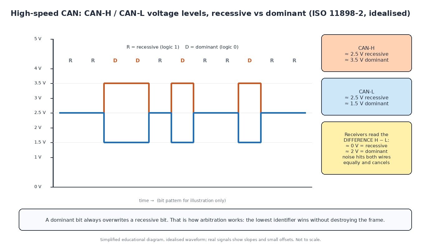
Most powertrain and chassis modules talk over high-speed CAN, two twisted wires called CAN-H and CAN-L. At rest (recessive) both sit at about 2.5 V. When a module sends a dominant bit, CAN-H rises to about 3.5 V and CAN-L falls to about 1.5 V. The receivers read the difference, about 0 V for recessive and about 2 V for dominant, which makes the bus very resistant to interference.
There is no master module. Each message starts with an identifier, and if two modules transmit together, the lower identifier wins arbitration because a dominant bit overrides a recessive one. The losing module simply waits and retries. Modules that keep producing errors eventually take themselves offline, which the ECU reports as “bus off”.
How the network is built
A typical car has several networks: a fast powertrain bus (commonly 500 kbit/s), one or more body or comfort buses, and LIN sub-buses for simple devices. A central gateway connects them and decides which messages pass between networks. Each high-speed bus has a 120 Ω terminating resistor at each end, often built into modules such as the engine ECU or the instrument cluster.

Two warnings before you measure. On many vehicles the OBD socket connects to the gateway or a separate diagnostic bus, so a reading at pins 6 and 14 describes that bus, not necessarily the powertrain network. And older fault-tolerant low-speed CAN (ISO 11898-3) uses a different termination scheme, so the 60 Ω rule only applies to high-speed CAN. Newer vehicles may also use CAN FD (up to 64 data bytes per frame) or Ethernet; check the wiring diagram first.
Step-by-step CAN bus diagnosis
- Read every module and note which ones are missing. If the TCU, ABS and cluster all report lost communication with the engine ECU, the ECU or its branch is the suspect. If everything reports everything, look at the whole bus.
- Check power and ground first. Measure battery voltage, fuses and module grounds under load. A module with a poor ground behaves exactly like a network fault, and a weak battery during cranking can set U-codes across the vehicle.
- Measure bus resistance with the battery disconnected. About 60 Ω between CAN-H and CAN-L means both terminations are present. About 120 Ω means one termination or one leg of the bus is open. Near 0 Ω means CAN-H and CAN-L are shorted together. Also check each line to ground and to battery positive for shorts.
- Check voltages with the ignition on. Both lines should sit near 2.5 V. A multimeter averages the traffic, so CAN-H reads slightly above 2.5 V and CAN-L slightly below. A line at 0 V or at battery voltage points to a short.
- Use a two-channel scope. Healthy CAN-H and CAN-L look like mirror images with clean square edges. Ringing or rounded edges suggest a termination problem; one flat line suggests an open or shorted wire.
- Unplug modules one at a time. Watch the scope or the scan tool while you disconnect each module. When the bus comes back, you have found the module or harness branch pulling it down.
Diagnostics on cars, trucks, tractors and bikes

On cars and vans, generic OBD-II/EOBD runs over CAN to ISO 15765-4, and service tools use UDS (ISO 14229) for fault memory, live data, coding and programming. Trucks and buses use SAE J1939, where faults are reported as an SPN (the parameter) plus an FMI (the failure mode), in DM1 messages for active faults, instead of P or U codes. Tractors and implements share ISOBUS (ISO 11783), which is based on J1939, so a faulty implement ECU or connector can disturb the tractor’s own bus. Many modern motorbikes run CAN between the ECU, ABS and dashboard, usually reached through a manufacturer-specific connector and adapter.
Before reading an ECU over OBD
An OBD read or write is a long UDS session over the same network. Connect a stable battery support unit rather than a small charger, keep the ignition state the tool asks for, and disconnect aftermarket trackers, dashcams or interfaces that sit on the bus. Some vehicles use a security gateway that blocks write access until the tool is authorised. If the bus shows errors or the gateway blocks access, fix the fault first or use a bench or boot connection, and always save the full original read.
Related fault codes (DTCs)
Generic OBD-II codes (SAE J2012) commonly seen with CAN communication faults. Wording varies by manufacturer and OEM-specific network codes are common, so always read every module.
| Code | Meaning | Typical causes |
|---|---|---|
| U0001 | High Speed CAN Communication Bus | CAN-H or CAN-L open or shorted, missing termination, a faulty module holding the bus |
| U0073 | Control Module Communication Bus “A” Off | Module went bus-off after repeated errors: wiring damage, short, water in a connector, module fault |
| U0100 | Lost Communication With ECM/PCM “A” | ECU power, ground or fuse fault, open CAN wires at the ECU, low voltage while cranking |
| U0101 | Lost Communication With TCM | TCU supply or ground, connector corrosion, CAN wiring to the TCU, TCU fault |
| U0121 | Lost Communication With Anti-Lock Brake System (ABS) Control Module | ABS module fuse or ground, damaged harness, water ingress, module fault |
| U0140 | Lost Communication With Body Control Module | BCM supply or ground, body bus or gateway wiring, module not waking |
| U0155 | Lost Communication With Instrument Panel Cluster (IPC) Control Module | Cluster power or ground, connector or wiring fault; on some cars the cluster holds a termination or gateway |
| U0401 | Invalid Data Received From ECM/PCM “A” | Messages arrive but fail checks: ECU internal fault, mismatched software or coding after replacement |
| P0600 | Serial Communication Link | Communication fault seen by the ECU; check power, grounds and the bus before condemning it |
| P0562 | System Voltage Low | Weak battery, charging fault or poor ground; often sets U-codes in many modules at once |
Closing
Power and ground, 60 Ω, 2.5 V, a clean scope pattern, then one module at a time: follow that order and most CAN faults are found in minutes.
Looking for an original stock ECU file for your vehicle? Browse the ECUFlashFiles catalogue.